transmission line theory
transmission lines
A transmission line is a connection that is capable of propagating an electromagnetic field signal in the longitudinal direction. When the physical dimensions of the device or the dimensions of the electrical connection are comparable to the wavelength of the signal, transmission line theory is needed to analyze it.
For example, a desk lamp with a 2-meter power cord whose power supply operates at 50 Hz has a wavelength of 6,000 kilometers.
λ=C/f=3.0*10^8/50=6000 0000 meters
In this way, the length of this power line is very short relative to the wavelength, and we can think of it as a short circuit and ignore it.
For a portable product such as a laptop, PDA, etc. PCB design, if the operating frequency is 100MHz, the transmission line effect must be considered.
λ = C/f = 3.0*10^8/100000000 = 3 meters
The product power cord 2 meters for 3 meters of operating frequency wavelength will have to be considered.
Characteristic impedance of the transmission line:
The characteristic impedance of a transmission line is the instantaneous impedance value seen on the transmission line as the signal propagates along the transmission line, where it is important to note that it is instantaneous, i.e., the impedance in a transient situation:
Characteristic impedance of transmission lines
This impedance is determined by the physical structure of the transmission line itself, which is generally designed to be 50 ohms, which was gradually formed during the development of microwave. The characteristic impedance of RF cables is around 70 ohms, when the transmission loss is minimized; in 30 ohms, when the transmission loss is minimized, the transmission loss is minimized.
Withstand the most power. Combining the two, 50 ohms was chosen as a standard to take care of both properties. If the impedance of an external device or cable does not match the characteristic impedance of the transmission line, reflections will occur.
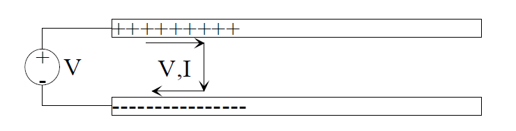
The reflection coefficient Γ of the transmission line and the signal reflection:
When the propagated signal of a transmission line reaches a node with an impedance discontinuity, the signal is reflected, just as the water surface fluctuates when water flows through the interface of a pipe of different caliber. The reflection coefficient Γ on the transmission line can be defined based on the ratio of the reflected voltage Vref to the incident voltage Vinc.
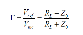
Transmission line reflection coefficient Γ formula
When the load impedance is greater than the input impedance, the reflection coefficient Γ > 0, the reflected signal is superimposed in the same direction as the incident signal; when the load impedance is less than the input impedance, the reflection coefficient Γ < 0, the reflected signal is subtracted from the incident signal. Discontinuities in the impedance of the transmission line do not only occur at the terminals, but also when the reflected signal is propagated to the source, secondary reflections are generated due to impedance discontinuities, and eventually, the signal is stabilized. The figure below shows the voltage changes at the source Vin and the load VL at the instant the signal jumps.
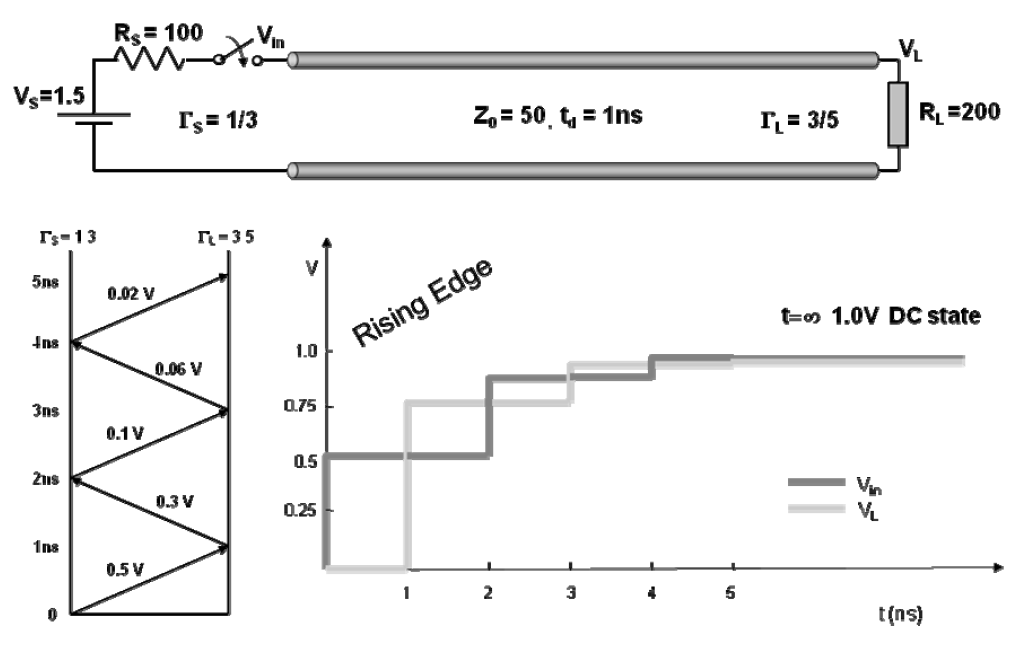
Voltage variations at source and load in the presence of reflections on the transmission line
- Created Date: 2025-03-07 16:05:49 ;
- Last modified on 2025-03-07 17:30:32 ;