
Introduction:
In the environment of the increasing number of modern electronic devices, proximity immunity testing has become an important part of ensuring the reliability and stability of the equipment, so the Ford EMC-CS-2009 standard and the ISO 11452-9 standard have proposed a hand-held transmitter RF immunity test program, the purpose is to assess the performance of automotive electronics in a variety of proximity electromagnetic interference, to ensure that the equipment in the practical applications can work normally. In this paper, we will introduce the purpose, method, standard requirements and analysis of the test results in detail.
I. Purpose of the test
Handheld transmitters are usually used to simulate the working status of cell phones, wireless communications, remote control and other devices, because they are used inside the car, so the RF field strength generated during their work will directly affect the stability of the automotive electronic components and equipment. So we need to evaluate the handheld immunity test by following Ford EMC-CS-2009 standard and ISO 11452-9 standard:
- Determine the ability of automotive electronic component equipment to operate in an EMI environment.
- Verify that the design of the equipment meets the relevant immunity requirements.
- Provide confidence in the product's market launch and user use.
- Meet the requirements of car manufacturers for component manufacturers.
II. Description of test criteria
The Ford EMC-CS-2009 standard covers the following main areas:
2.1. test environment:
It is specified that the tests shall be conducted in an ALSE radio darkroom as required by ISO 11452-2 to ensure the accuracy of the test results. In addition, Section 11.6.1 of the standard specifies the use of hand-held test antennas in three different frequency bands manufactured by Schwarzbeck, Inc. as listed below:
- SBA 9113 components 420 NJ Tests near-field handheld transmitters in the 360MHz-2700MHz frequency range for RF immunity testing applications.
- If the car factory has higher testing needs, you can also purchase the SBA 9119 + 422 NJ Test frequency range 900MHz-6GHz.
- There's also 419 NJ + NMHC 4MM : Measurable frequency 20MHz-220MHz
All three antennas can be tested using the test methods described below. However, regardless of which antenna frequency band is used, your test equipment and test frequency range should be noted in the test report.
2.2. Test distance provisions:
The standard requires the DUT to use different test distances in the following two cases. The recommended test antenna 420NJ mentioned in the previous section has a 50mm test distance option that can be tested directly after connection, and when the option is removed the test can be started at a 5mm test distance.
<<<<提醒:左右滑动表格>>>>| Different types of DUT surfaces and harnesses | Test Distance of Handheld Transmitter Antenna and DUT |
| The surface of the DUT and the first 300 mm of its harness (measured from the DUTconmector), the These harnesses may be packaged in intentional and/or unintentional locations from 50 to 200 mm. Handheld transmitters may be located in these positions. | 50mm Antenna needs to be moved 100mm at a time Test area: 100mm*100mm |
| keys and similar devices that may come into direct contact with handheld transmitters and all other DUT surfaces. As well as the first 300mm of its harness, these harnesses may be packed less than 50mm from the intentional storage location. | 5mm Antenna needs to be moved 30mm at a time Test area: 30mm*30mm |
Regardless of whether the cable in the table above or the surface of the EUT is being tested, in each test area that has been identified, the handheld test antenna needs to be rotated 90 degrees to test both polarization directions and to observe the DUT operating status for writing the test report.
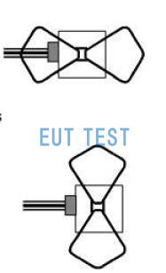
Handheld test antennas require a 90-degree turn to test both polarization directions.
2.3. Required test equipment and test configuration diagrams:
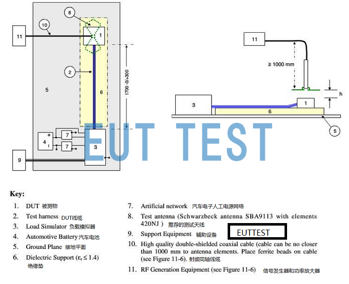
Diagram of test equipment and test configuration required for handheld transmitter immunity testing
Testing requires preparation of all test equipment and test accessories called for in the configuration diagram above:
- DUT: Automotive electronic parts and equipment to be tested, DUT is also known as EUT.
- DUT Cables: All interconnecting cables required for the operation of the DUT.
- Load simulator: simulating automotive electronic loads
- Car battery: 12V or 24V battery
- Ground plane: reference ground plane, need to change the flat area according to the size of the object to be measured. Contact EUTTEST to customize large copper or aluminum plates.
- Insulating mats: relative dielectric constant < 1.4, customized size and thickness by contacting EUTTEST.
- Artificial Power Networks for Automotive Electronics: AN in compliance with CISPR25 requirements
- Test Antenna: 420NJ , SBA 9113, 422NJ, SBA 9119
- Auxiliary equipment: other equipment required for the normal operation of the DUT
- High-quality RF cables: contact EUTTEST for customized RF cables for different frequency ranges.Low Loss RF CablesThe
- Signal generators and power amplifiers: signal sources and amplifiers that generate the required test frequencies
2.4, Test Methods:
2.4.1, Calculate forward input power
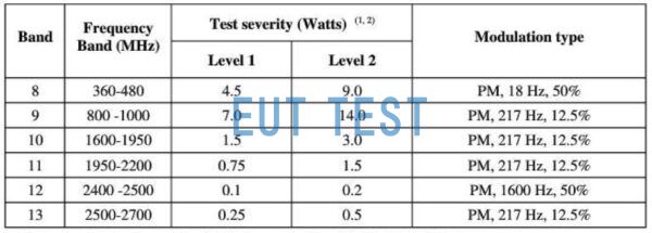
Test Frequency and Input Power Requirements for Handheld Transmitter Antennas
After setting up all the test equipment and accessories, you need to calculate the output power of the front end of the antenna according to the table above, and then calculate the electric field strength output from the antenna according to the following.
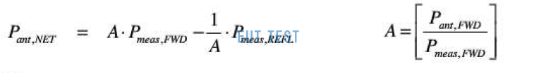
Antenna front-end output power calculation formula
- Pant: the input power of the antenna, refer to the image above: Test Frequency and Input Power Requirements for Handheld Transmitter Antennas
- A: cable loss, A<1
- Pfwd forward power: forward power from the directional coupler
- Pref Reverse Power: Reverse power from the directional coupler
The forward power of the amplifier output can be calculated by the above formula.
2.4.2 Data recording and analysis
During the testing process, the performance data of the equipment is recorded in real time, especially the specific situation of malfunction or abnormal function. At the end of the test, the recorded data are organized and analyzed to determine whether the immunity performance of the equipment meets the standard requirements.
2.4.3 Analysis of test results
The test results will be evaluated based on the performance of the device under interference conditions. If the equipment works properly under all interference signals, it is considered to have met the requirements of the Ford EMC-CS-2009 standard for immunity; if it functions abnormally under certain conditions, the cause should be further analyzed and design improvements should be made.
reach a verdict
Ford EMC-CS-2009 standard provides a systematic and scientific basis for RF immunity testing of handheld transmitters. By testing in strict accordance with the standard, the performance of the equipment in the electromagnetic interference environment can be effectively evaluated, providing strong support for product quality assurance and market competitiveness.
The above is a detailed description of Ford EMC-CS-2009 Testing Handheld Transmitter Immunity, covering test objectives, criteria, methods and results analysis. We hope it can help the related personnel in their work.