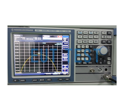
This article introduces the military equipment testing EMC should be in accordance with the standard GJB151B-2013 on the performance requirements of the receiver and signal generator to prepare for the standard electromagnetic compatibility test instrumentation. For the EMI part of the test, we need to pay attention to the relevant requirements and important settings of the EMI receiver; for the EMS part, we need to pay attention to the important settings of the signal generator such as step and modulation.
GJB151B-2013 Performance Requirements for EMI Test Receivers:
When performing EMI-related tests, we focus onEMI Test ReceiverIt is sufficient if the performance indicators of the receiver meet the requirements of the standard. For any frequency selective EMI measurement receiver purchased from EUTTEST, as long as its performance (e.g., sensitivity, bandwidth, detector, dynamic range and operating frequency, etc.) meets the requirements specified in this standard, it can be used for the tests specified in the GJB151B-2013 standard. Typical EMI receiver instrument characteristics requirements see GBT 6113.101.
Oscilloscopes and their probesIt should have sufficient bandwidth, sampling rate, dynamic range and other performance parameters to meet the needs of the test.
Detector Requirements for Receivers
Peak detectors should be used for both transmit and sensitivity tests performed in the frequency domain. The peak detector detects the peak of the modulation envelope in the passband of the receiver. The receiver uses a root-mean-square detector that produces a sine wave with the same peak indication. When test instruments with other detection methods (e.g., oscilloscopes, non-selective voltmeters, or broadband field strength meters) are used for sensitivity testing, the measurements are corrected so that the readings are corrected to the equivalent root-mean-square value of the peak of the modulation envelope. The correction factor can be determined by comparing the response of the detector to signals with equal peak levels with and without modulation.
Computer-controlled instruments
The manufacturer, model, and version of the test software should be provided in the test report.
Receiver test bandwidth settings
The transmit test shall use the measured receiver bandwidth listed in Table 2. This bandwidth is the 6 dB bandwidth of the total receiver selectivity curve. Video filters should not be used to limit the receiver response. If the receiver has a controllable video bandwidth, it should be tuned to its maximum value.
Table 2 Bandwidth and measurement time
<<<<提醒:左右滑动表格>>>>| Frequency range | 6dB bandwidth RBW kHz | gaze durationª S | Minimum measurement timeª |
| 25Hz~lkHz | 0.01 | 0.15 | 0.015s/Hz |
| 1kHz~ 10kHz | 0.1 | 0.02 | 0.2s/kHz |
| 10kHz~150kHz | 1 | 0.02 | 0.02s/kHz |
| 150kHz~ 30MHz | 10 | 0.02 | 2s/MHz |
| 30MHz~1GHz | 100 | 0.02 | 0.2s/MHz |
| > 1GHz | 1000 | 0.02 | 20s/GHz |
| a Optional scanning technique: When using the maximum value hold function and the total scanning time is not smaller than the minimum measurement time specified above, multiple scans with faster scanning speeds can be used instead. Additional options are required to meet the bandwidth when testing with a spectrometer. | |||
forensics
All transmissions regardless of their characteristics, i.e., whether broadband or narrowband signals, shall be tested using the measured receiver bandwidths specified in Table 2 and compared to the limits in this standard.
frequency scan
For emission tests, each applicable test should be scanned over the entire frequency range. The minimum measurement time for analog measurement receivers is shown in Table 2. Digital receivers shall be swept in steps no larger than half a bandwidth and with dwell times in accordance with Table 2. If the provisions of Table 2 are not sufficient to capture the maximum emission of the EUT, the frequency sweep time shall be increased.
4.3. 11.4.4 Launch data logging
The amplitude-frequency curve of the emission data shall be generated and displayed continuously and automatically during the test. The displayed information shall account for all correction factors (transducer, attenuator, cable loss, and similar) and include the appropriate limit values. The plotted transmit test curve shall have a frequency resolution of 11 TP3T of the frequency under test or twice the bandwidth of the measuring receiver (whichever is greater) with a minimum amplitude resolution of 1 dB.
Evaluation of test results
In this standard, the evaluation of test results is based on direct test data, without considering the measurement uncertainty.
For the EMI test, the test results less than or equal to the limit value is in compliance with the standard requirements, otherwise it is exceeded.
GJB151B-2013 Performance Requirements for Signal Sources When Conducting EMS Sensitivity Tests:
frequency scan
For sensitivity tests, each applicable test shall be swept over the entire frequency range. For sensitivity sweep tests, the generator sweep rate and frequency step shall not be greater than the values shown in Table 3. The rate and step size are determined using the generator tuning frequency ƒ0The multiplication factor is expressed as a multiplication factor. Analog sweeps refer to sweeps that are continuously tuned to Novo, and step sweeps refer to sweeps that are sequentially tuned at discrete frequency points. For step sweeps, a response time of at least 3s or EUT (whichever is greater) resides at each tuning frequency. To observe a reliable response, the scan rate and step size should be reduced if necessary.
Table 3 Sensitivity scan parameters
<<<<提醒:左右滑动表格>>>>| Frequency range | Analog Scanning Extreme Scan Rate | Maximum step size for step scanning |
| 25Hz~1MHz | 0.0333ƒ0/s | 0.05ƒ0 |
| 1MHz~ 30MHz | 0.00667ƒ0/s | 0.01ƒ0 |
| 30MHz~1GHz | 0.00333ƒ0/s | 0.005ƒ0 |
| 1GHz~40GHz | 0.00167ƒ0/s | 0.0025ƒ0 |
Modulation of sensitivity signals
The sensitivity test signals of CS114 and RS103 were modulated with 1kHz, 50% space-ratio pulses (on/off ratio not less than 40dB).
Note: After being continuously modulated with the above j pulses, the commercial level and the low level each take up half of the time. A high level is indicated by an "on" signal output, while a low level is indicated by an "off" signal output. Theoretically, the low level is zero volts, but in practice, there will be a residual disk. This standard uses the "on/off ratio" parameter to limit the size of the residual component.
sensitivity criterion
Generally specified by the product specification into a test outline. Sensitivity criteria should be documented in the EMC test report.
Sensitivity threshold level
All sensitivities and anomalies that occur during the test shall be recorded. When the EUT is sensitized during the test, the sensitivity shall threshold level shall be determined when the sensitization just does not occur. The sensitivity threshold level shall be determined and included in the EMC test report as follows:
- When sensitization occurs, reduce the interfering signal level until the EUT returns to normal;
- Continue to reduce the interfering signal level by 6 dB;
- Gradually increase the interfering signal level until the sensitivity phenomenon is just repeated, at which time the interfering signal level is the sensitivity threshold level;
- Record the sensitive should threshold level, the frequency range, the most sensitive frequency and its level, and other applicable test parameters.
Calibration of test equipment
The test equipment and accessories required by this standard shall be calibrated in accordance with the relevant provisions of the figure family. Unless otherwise specified, measurement antennas, current probes, field sensors, LISNs (see Figure 7 for impedance requirements), and other devices in the measurement path shall be calibrated at least once every two years.
Calibration of the test system
Prior to the start of each launch test, the test system (including Laos receivers, cables, attenuators, phasers, etc.) shall be calibrated by injecting a known signal and monitoring the output of the system in accordance with the provisions of the respective test method. For multiple, uninterrupted repetitive tests with the same equipment, e.g. for different operating states of the EUT, the system needs to be calibrated only once.
radiance factor
Measurement of antenna coefficients of antennas phi GJB/J 54 10 calibration.


