Introduction:
CS114 is one of the test items of GJB151B-2013, this article mainly introduces CS114 test methods and test equipment and other requirements, the required test equipment our company have agents to sell, details click the text link below to view the specific test instruments.
CS114 Scope of application
This item CS114 test applies to all interconnecting and power cables.
CS114 Limit
When a test signal calibrated in accordance with Figure 39 and modulated as required by 5.16.3.3 c) 2) is fed to the injection probe, the EUT shall not exhibit any malfunction, degradation of performance, or deviation from the specified metric values, or exceed the metric tolerances given in the individual equipment and subsystem specifications. Select the applicable limit curves in Figure 39 in accordance with Table 12. If the actual induced current on the cable under test is 6 dB above the limit, the EUT is considered to satisfy the requirement when it is insensitive even if the positive power level monitored on the directional phasers is below the check value....
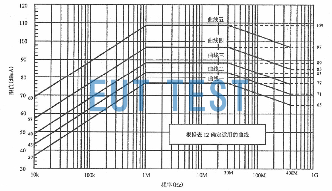
Figure 39 CS114 Checksum Limits
For EUTs installed on ships or submarines, if the power generating equipment is a causal class power supply, there is an additional requirement for the EUT complete power cable (high potential line + return line, common mode) to have a limit of 77 dBμA in the frequency range of 4 kHz to 1 MHz. If necessary, the ordering party can also extend the frequency below 4 kHz.
At 200MHz to 400MHz, the repeatability of test results may be problematic due to possible resonance. Whether or not to test in this band is specified by the ordering party.
This item does not apply to coaxial cables for receiver antennas, except for surface ships and submarines.
CS114 Test Equipment
The test equipment is as follows:
- Current Injection Probes (See Figure 40 for insertion loss requirements and Figure 41 for test methods).
- Current Monitoring Probes
- Calibration device: Coaxial transmission line with 50 Ω characteristic impedance. It has coaxial connectors at both ends and provides enough space around the center conductor for the calibration injection probe.
- directional coupler
- Coaxial Load, 50Ω
- Power amplifier
- 20dB Attenuator, 50Ω;
- Measurement receivers;
- current probe;
- signal generator;
- Data logging device;
- oscillographThe input impedance is high resistance;
- Resistors;
- Military LISNThe
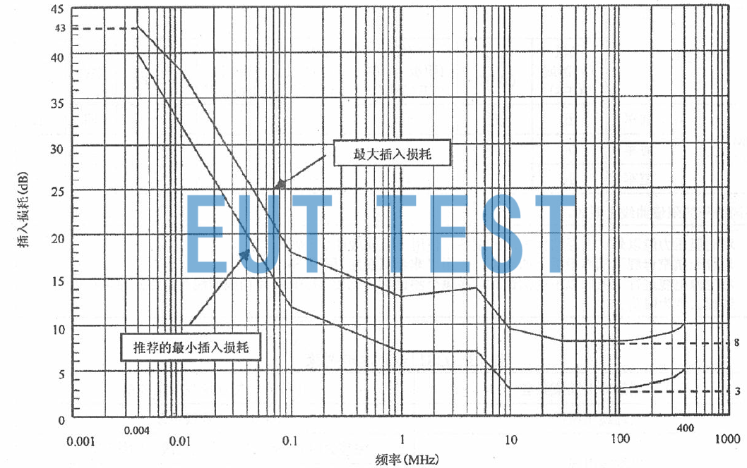
Figure 40 Insertion Loss Requirements for CS114 Injection Probes
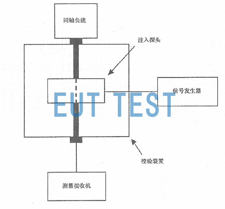
Figure 41 CS114 Injection Probe Insertion Loss Measurements
The insertion loss of the injection probe is equal to the difference between the input power of the injection probe and the input power of the measurement receiver.
CS114 Test Configuration
The test configuration is as follows:
a) Perform basic configuration according to 4.3.9 and Figures 2 to 5 of GJB151B.
b) Calibration
Perform the calibration according to Figure 42 and the following steps:
1) Snap the injection probe onto the center conductor of the calibration device;
2) One end of the calibration device is connected to a 50 Ω load and the other end is connected to the measurement receiver A through an attenuator.
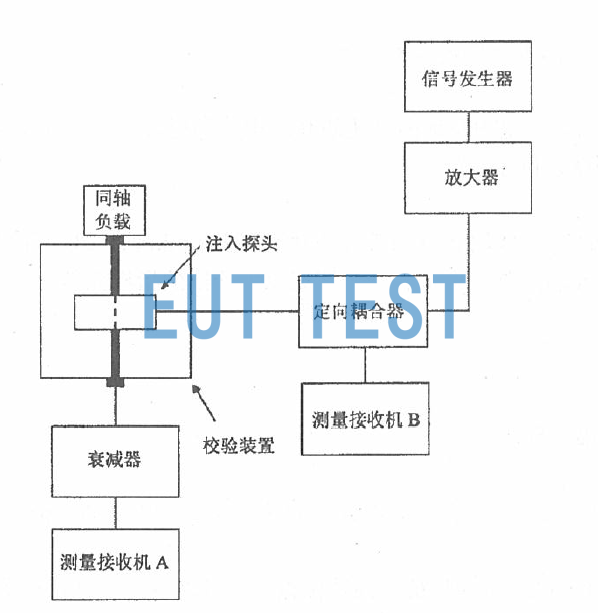
Figure 42 CS114 Checksum Configuration
c) EUT testing
Test the EUT according to Figure 43 and the following steps:
1) Snap the injection probe and monitoring probe onto the cable bundle connected to the EUT connector.
2) To minimize errors, connect to the monitoring probe with the same test configuration as the calibration (receiver, coaxial cable, feed-through connector, additional attenuator, etc.). Additional attenuation may be added when required.
3) Place the monitoring probe 5 cm from the EUT connector, or as close as possible to the connector housing if the connector and its housing are longer than 5 cm in total length.
4) Place the injection probe 5 cm from the monitoring probe.
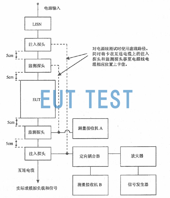
Figure 43 CS114 Test Configuration
CS114 Test Procedure
For testing, follow the steps below:
a) The test equipment is energized and warmed up and reaches a stable working condition.
b) Calibration
1) Tune the signal generator to 10kHz without modulation;
2) Increase the signal level and use Receiver A to monitor the current flowing through the center conductor of the calibration device up to the current specified in the standard;
3) Record the forward power measured by Receiver B feeding into the injection probe;
4) Scan across the test band and record the forward power required to achieve the required current.
c) EUT testing
Each cable bundle terminated by each connector on the EUT is tested according to Table 13 and the following procedure:
1) The EUT is powered on to warm up and reach a stable working condition.
2) Tune the signal generator to 10 kHz and modulate it with a pulse with a l kHz duty cycle of 50%.
3) Feed the positive power determined by 5.16.3.3 b) 4) into the injection probe while monitoring the induced current.
4) The forward power is the smaller of the following two powers when scanning over the test frequency range according to 4.3.11. 5. 1 and Table 3:
I I Positive power as determined by 5.16.3 .3 b) 4);
I I The monitoring current is equal to the positive power at the sum of the corresponding limit current and 6 dB.
5) Monitor for degradation of EUT performance. If sensitization occurs, determine the sensitivity threshold level per 4.3.11.5.4.
6) Repeat 5.16.3.3 c) 2) ~ 5.16.3.3 c) 5) per Table 13 for each cable bundle connected to each of the other EUT connectors.
7) For EUTs with redundant cables for security reasons, e.g. multiplexed data buses, testing may be carried out using the simultaneous injection of multiple cables method.
CS114 Test Data
Upon completion of the test, the following test data is required:
a) Limits, actual applied amplitude-frequency curves, or data sheets;
b) A statement of whether the sensitivity requirements are met for each cable under test;
c) The cable bundles, frequencies, sensitivity threshold levels and their operating status to which the EUT is sensitive.
Table 12 CS114 Limit Lines
<<<<提醒:左右滑动表格>>>>| Frequency range | Platform | ||||||||
| Aircraft (external or SCES) | Aircraft (internal) | Ship (on deck) and underwater (external)a | Metal ships (below deck) | Non-metallic ships (below deck)b | underwater (internal) | ground level | Space systems | ||
| 4kHz~1MHz | naviesC | / | / | 77dBμA | 77dBμA | 77dBμA | 77dBμA | / | / |
| 10kHz~ 2MHz | army | 5 | 5 | 5 | stupid (Beijing dialect) | 4 | "one" radical in Chinese characters (Kangxi radical 1) | 4 | surname San |
| navies | 5 | 5 | 5 | stupid (Beijing dialect) | 4 | "one" radical in Chinese characters (Kangxi radical 1) | stupid (Beijing dialect) | surname San | |
| air force | 5 | surname San | / | / | / | / | stupid (Beijing dialect) | surname San | |
| 10kHz~ 2MHz | army | 5 | 5 | 5 | stupid (Beijing dialect) | stupid (Beijing dialect) | stupid (Beijing dialect) | 4 | surname San |
| navies | 5 | 5 | 5 | stupid (Beijing dialect) | stupid (Beijing dialect) | stupid (Beijing dialect) | stupid (Beijing dialect) | surname San | |
| air force | 5 | surname San | / | / | / | / | stupid (Beijing dialect) | surname San | |
Table 12 (continued)
<<<<提醒:左右滑动表格>>>>| Frequency range | Platform | ||||||||
| Aircraft (external or SCES) | Aircraft (internal) | Ship (on deck) and underwater (external)a | Metal ships (below deck) | (below decks of non-metallic ships)b | Underwater (internal) | ground level | Space systems | ||
| 200MHz~ 400MHz | army | 5 | 5 | 5 | stupid (Beijing dialect) | stupid (Beijing dialect) | "one" radical in Chinese characters (Kangxi radical 1) | 4 | surname San |
| naviesC | / | / | 5 | stupid (Beijing dialect) | stupid (Beijing dialect) | "one" radical in Chinese characters (Kangxi radical 1) | stupid (Beijing dialect) | surname San | |
| air force | 5 | surname San | / | / | / | / | stupid (Beijing dialect) | surname San | |
| Limit curves for different numbers are shown in Figure 39 | |||||||||
| a For equipment outside the pressure chamber of a submarine and within the superstructure, use "metal ship (below deck)". b For equipment located on the deck of aircraft hangars on aircraft carriers, use "non-metallic ship (below deck)". e When testing the source cable below IMHz, at each test frequency point, compare the magnitude of 77 dBμA with the corresponding curve at that frequency point, and select the larger value as the limit. | |||||||||
Table 13 CS114 Tested Cable Bundles
<<<<提醒:左右滑动表格>>>>| Type of cable bundle terminated by connector | Current probe every time the cable bundle is jammed |
| interconnecting cable | complete interconnecting cable |
| Power cord cable | Complete power cables (including high potential, return and ground) |
| All high potential wires (excluding power return and ground) | |
| Cables including interconnectors and power cords between times | Complete cable |
| Complete power cables (including high potential, return and ground) | |
| All high potential wires (excluding power return and ground) |