CE101 Introduction:
CE101 is a power cord conducted emission test item below 10kHz required by both GJB151B-2013 and MIL-STD-461F standards. This article mainly introduces the applicable product scope, limit line, required test instruments, test layout, test methods and procedures of CE101 test required by military EMC standards. For more details, please refer to the introduction of CE101 25Hz-10kHz Conducted Emission of Power Cord standard analysis below.
See more military equipment EMC test programs:Introduction to EMC Test Items Required by MIL-STD-461F StandardThe
Scope of application
The CE101 25Hz-10kHz Power Line Conducted Emission Test Program applies to equipment power lines, including trap lines, on surface ships, submarines, Army aircraft (including airport maintenance work areas), and Navy aircraft. These power lines are powered from an external source other than the EUT.
For equipment on Army aircraft (including airport maintenance work areas) and Navy aircraft using AC power, the starting frequency for this item begins at the second harmonic of the power supply frequency: for equipment installed on Navy aircraft, this item applies only to ASW aircraft.
This item also applies to space systems when specified by the ordering party.
When the operating current of the EUT is too high and 50 μH LlSN cannot meet the test requirements, theAppendix B EUT Power Port Conducted Emission Substitution Methods, subject to the consent of the ordering party.
CE101 Limit line
Power line conducted emissions should not exceed the limits in figures 8 through 11, where figure 8 applies to submarines, figures 9 through 10 to surface ships and submarines, and figure 11 to Navy ASW aircraft, Army aircraft (including airfield maintenance work areas); figure 11 also applies to space systems when specified by the ordering party.

Figure 8 CE101 limits applicable to submarines (DC)

Figure 9 CE101 limits for surface ships and submarines (50 Hz)

Figure 10 CE101 limits for surface ships and submarines (400 Hz)

Figure 11 CE101 Limits Applicable to Navy ASW Aircraft, Army Aircraft (Including Airport Maintenance Work Areas), and Space Systems
List of CE101 utilization test frequencies:
<<<<提醒:左右滑动表格>>>>| CE 101 Test Frequency Range - DC Power Supplies - Submarines | 25Hz-10kHz |
| CE 101 Test Frequency Range - 50Hz Power Supply -Surface ships and submarines | 50Hz-10kHz |
| CE 101 Test Frequency Range - 400Hz Power Supply -Surface ships and submarines | 400Hz-10kHz |
| AC/DC Power Navy ASW Aircraft, Army Aircraft (including Airport Maintenance Work Areas) and Space Systems | 25Hz-10kHz |
CE101 Test Equipment
EUTTES offers the following test equipment for CE101 test systems in accordance with GJB151B-2013:
- Measurement receivers;
- current probe;
- signal generator;
- Data logging device;
- oscillographThe input impedance is high resistance;
- Resistors;
- Military LISNThe

Fig. 6 Circuit diagram of 50μH LISN

Fig. 7 50μH LISN impedance
CE101 Test Configuration
The test configuration is as follows:
Per GJB151B-2013 How to Select the Correct Test Layout Based on the DUT for Basic Configuration Fig. 2 - Fig. 5 in the diagram.
system validation
Configure as in Figure 12.

Figure 12 CE101 Test System Calibration Configuration Diagram
EUT test
- Configured per Figure 13;
- Place the current monitoring probe 5 cm from the LISN.
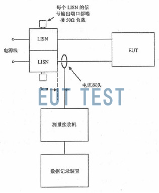
Figure 13 CE101 Test Configuration
CE101 Test Procedure
For testing, follow the steps below:
a) The test equipment is energized and warmed up and reaches a stable working condition.
CE101 test system calibration and calibration methods
1) Apply the 1kHz, 3kHz and 10kHz calibration signals to the current probe respectively, with the signal level at least 6dB below the limit;
2) Measure the current level with an oscilloscope and resistor while checking that the current waveform is a positive strong wave;
3) The measurement receiver is scanned in the normal data scanning mode to confirm that the measured value is within ±3dB of the oscilloscope current measurement;
4) If the measured value deviates by more than ±3 dB, identify the cause of the error and correct it before testing.
EUT test procedure for CE101
1) The EUT is energized to warm up and reach a stable working condition;
2) Snap the current probe onto one of the power cords to be tested;
3) The measurement receiver sets the bandwidth and measurement time according to Table 2 and scans in the applicable frequency range;
4) Repeat 5 .4 .3 .3 c) 3) for each of the other power cords tested;
5) The magnitude of the fundamental current can be directly adopted from the measurement data of the above current probe at the fundamental frequency: the magnitude of the DC load current can be measured by a caliper-type meter with DC current measurement function.
CE101 Test Data and Test Report
Upon completion of the test, the following test data is required:
a) Plot the spectrum of the test data continuously and automatically on the X-Y coordinates;
b) The applicable limit curves are shown on the graph;
c) List the required frequency, amplitude, and amount of exceedance of limits and their operating status.