
Introduction:
GB/T 42968.2-2024 has been officially released and implemented on October 26, 2024, which makes us no longer limited to using the old YD/T 1690.2-2007 standard to complete theEMC Testing of Integrated CircuitsIn the radiation immunity test project, the new standard defines how to use the national standard GB/T 42968.2-2024 TEM chamber to measure the immunity of integrated circuits to electromagnetic radiation analysis test. Here is some information about GB/T 42968.2-2024.
National standard number and name of the standard:
Standard number:GB/T 42968.2-2024
Chinese Name:Integrated Circuit Electromagnetic Immunity Measurements Part 2: Radiated Immunity Measurements TEM Chamber and Broadband TEM Chamber Methods
English name: (equivalent to international standard IEC 62132-2:2010)Integrated circuits-Measurement of electromagnetic immunity-Part 2: Measurement of radiated immunity- TEM cell and wideband TEM cell method
Official release date:October 26, 2024
Official implementation date:October 26, 2024
Alternative standards:YD/T 1690.2-2007 Technical Requirements and Measurement Methods for Diagnosis of Internal Electromagnetic Emission of Telecommunication Equipment (150kHz~1GHz) Part 2: Radiated Emission Measurement TEM Cell and Broadband TEM Cell Methods
Standard Requirements:
GB/T 42968.2-2024 proposes test methods for TEM cell, broadband TEM or GTEM cell.
Extended Reading:IC EMC Integrated Circuit EMC Sources of Problems
GB/T 42968.2-2024 Introduction and requirements for TEM cell:
TEM Cell Introduction:
The TEM cell provides a broadband method for measuring the immunity of a DUT to fields generated within the cell or radiated emissions from a DUT placed within the cell. It eliminates the bandwidth, nonlinear phase, directivity, and polarization measurement limitations inherent in the use of conventional antennas.TEM (Transverse Electromagnetic Mode) The cell is an extended transmission line used to propagate a TEM wave from an external or internal source. The wave is characterized by transverse orthogonal electric (E) and magnetic (H) fields that are perpendicular to the direction of propagation along the length of the chamber or transmission line. The field simulates a planar field generated in free space with an impedance of 377 Ω. The TEM mode has no low-frequency cutoff. This allows the CELL to be used at the desired low frequencies.15 The TEM mode also has a linear phase and constant amplitude response as a function of frequency. This allows the cell to be used to generate or detect known field strengths. The upper effective frequency limit of the cell is limited by the resonance that occurs within the cell and the distortion of the test signal due to multimode. These effects are a function of the physical size and shape of the TEM cell.
For example, the size and shape of the 1 GHz TEM cell has impedance matching at the input and output feed points of the cell, which limits the VSWR to less than 1.5 below the rated frequency. each end of the cell is tapered to fit a conventional 50 Ω coaxial connector and is equipped with an access port to accommodate the IC test board. The first resonance is demonstrated by the high VSWR in a narrow frequency range. the high Q of the CELL is responsible for this high VSWR. The proven maximum frequency field generation of the CELL is also suitable for emission measurements at this frequency.
Learn more about:IC Reactions induced by electromagnetic field coupling of integrated circuit chips
Extended Reading:TEM-cell Test Guide for Radiated Emissions and Radiated Immunity
Requirements for the technical specifications of the TEM cell:
The standard requires that the TEM cell used for this test procedure be a two-port TEM waveguide equipped with an EUT adapter port sized to match the EMC test adapter plate.The TEM cell should not have higher-order modes in the frequency range measured. For this procedure, the recommended TEM cell frequency range is from 150 kHz to the first resonance frequency of the lowest high-order mode (typically <2 GHz). Only a single cell should be used to cover the frequency range being evaluated, and the VSWR of the TEM cell should be less than 1.5 over the frequency range being measured.
However, due to the potential for error in calculating the applied electric field, TEM cells with a VSWR less than 1.2 should be preferred.TEM cells with a VSWR less than 1.2 do not require field strength characterization.TEM cells with a VSWR greater than or equal to 1.2, but less than 1.5, should be characterized in accordance with the procedures in Annex A. The VSWR of the TEM cell should be determined by the VSWR of the cell. VSWR data for the original TEM cell (within the measured frequency range) shall be included in the test report. Measurements obtained from TEM cells with a VSWR less than 1.2 will be superior to data obtained from TEM cells with a higher VSWR.
GB/T 42968.2-2024 Introduction and requirements for broadband TEM or GTEM:
An introduction to broadband TEM or GTEM:
A broadband TEM or GTEM cell is an extended transmission line that does not convert back to a 50Ω feed like a conventional TEM cell, but instead expands and terminates with a diaphragm load and RF absorbing material. The cell avoids the modification limitations of a conventional TEM cell, so its available upper frequency is not limited by its size, but by the characteristics of the RF absorber and diaphragm termination. The broadband TEM cell can be of virtually any practical size with a usable frequency range up to 18 GHz.
The GTEM cell offers the potential to extend the upper frequency limit for radiated immunity measurements beyond the 1 GHz to 2 GHz limit of the TEM cell. For example, to be able to properly evaluate ICs that use clock frequencies near or above 1 GHz, the extended frequency limits are needed.
In addition, the larger size of the GTEM cell provides the ability to evaluate ICs requiring PCBs larger than the default size defined in IEC 62132-1. As with any other modification of this test method, the PCB dimensions can be extended as agreed between the manufacturer and the user and should be carefully documented in the test report.
Technical requirements for broadband TEM or GTEM:
The GHz or broadband TEM (GTEM) cell used for this test procedure is a single-port TEM waveguide and should be equipped with an adapted placement port that matches the EMC test board.The GTEM cell should not have higher-order modes in the frequency range measured. For this procedure, the recommended GTEM cell frequency range is from 150 kHz to the first resonance frequency of the lowest high-order mode (typically >2 GHz). A single chamber should be used to cover the frequency range being evaluated.
GTEM cells shall have a VSWR of less than 1.5 over the frequency range measured; however, due to the potential for error in calculating the applied electric field, GTEM cells with a VSWR of less than 1.2 are preferred GTEM cells with a VSWR of less than 1.2 do not need to be characterized in terms of field strength GTEM cells with a VSWR of greater than or equal to 1.2, but less than 1.5, shall be characterized in accordance with the procedures in Appendix A. Raw GTEM cell VSWR data (over the measured frequency range) shall be included in the test report. Measurements obtained from GTEM cells with VSWR less than 1.2 will be prioritized over data obtained from GTEM cells with higher VSWR.
A diagram of the test layout of the chip under test required by the standard:
The EMC test adapter board with the IC chip under test installed should be mounted on the adapter port of the TEM cell or GTEM cell, with the DUT facing the TEM's diaphragm board, as shown in the figure below:
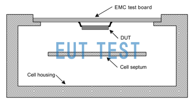
Installation of DUT test adapter boards on TEM CELL adapter ports
After the correct installation of the adapted circuit board, you can use an external signal source, power amplifiers to inject RF power into the input port of the TEM began to radiate the electric field to the chip under test, it is important to note that the need to test the need to constantly pay attention to and monitor the operating state of the chip under test, and write in the test report.
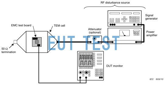
Injection of RF power into the TEM cell using signal sources, amplifiers and other equipment
The same equipment is used when injecting with the GTEM cell, but the GTEM can hold a larger DUT than the TEM cell because it has a measurable area size of up to 1 meter high, whereas the TEM cell has a measurable area of only 10 cm. It is up to you to choose the right test method for your product needs.
Optional TEM cell testing instrumentation:
If you need your company's IC products according to GB/T 42968.2-2024 using TEM small chamber to measure IC electromagnetic radiation immunity to measure the immunity performance of integrated circuits, you can purchase the following equipment for testing and use, EUTTEST provides a complete chip EMC test program and after-sales training services.
In addition, if you do not want to purchase IC EMC test equipment, we also provide services to help you test chip EMC. Please contact us for more information.
- Integrated circuit test equipment
- FCC-TEM-JM7B TEM-cell 10kHz-3GHz(small chip size), 250W power injection
- fcc-tem-jm7c tem-cell dc-8ghzWideband, 250W Power Injection
- FCC-TEM-JM7D TEM-cell 10kHz-3GHz(large size chip), 250W power injection
Relevant criteria:
There is a complete set of EMC test standards for EMC of IC chips, including domestic and foreign IEC publications, for details, click the following link to learn more about IC-EMC test standards related content:
What are the EMC test standards for integrated circuits