
Introduction:
The new version of the GB4343.1-2024 standard was released on May 28, 2024 and will be implemented on June 01, 2026, and is still in use asGB4343.1-2018 Standard. Check out the following to learn what basic information updates and standard content updates are available in GB 4343.1-2024 vs. the 2018 version of the standard update content analysis.
Comparison of GB4343.1-2024 and 2018 standard basic information updates:
The name of the standard remains unchanged:
GB 4343.1-2018 Electromagnetic compatibility requirements for household appliances, power tools and similar apparatus Part 1 Emission
GB 4343.1-2024 Electromagnetic compatibility requirements for household appliances, power tools and similar apparatus Part 1 Emissions
Revised citation standards:
CISPR 14-1:2018, published in 2018, references and adopts equivalently the CISPR 14-1:2011 standard;
CISPR 14-1:2024, published in 2024, references and adopts equivalently the CISPR 14-1:2020 standard;
Defines the latest implementation date:
The standard requires that from 2026-06-01 all applicable household appliances and similar products will need to pass the new version of GB 4343.1-2024 for CCC mandatory certification.The
Comparison of GB4343.1-2024 and GB4343.1-2018 standard content updates:
The following table lists the details of the 2024 version and the 2018 version of the updated standard. This table no longer lists the original content of GB4343.1-2018, for the original text of the 2018 standard you can view: GB4343.1-2018 standard content.
<<<<提醒:左右滑动表格>>>>| GB4343.1 2024 standard original content | Update notes for 2024 vs. 2018 version |
| This document specifies requirements for the emission of radio-frequency nuisance in the frequency range of 9 kHz to 400 GHz, and applies to electrical household appliances power tools and similar apparatus, as defined below, regardless of whether the mode of power supply is alternating current (AC) or direct current (DC) (including batteries). This document applies to the following equipment. Household appliances or equipment for similar purposes. Note 1: Examples of device applications are as follows. -Used for typical domestic functions in the family environment, including the home and its associated buildings, gardens, etc.. -For typical housekeeping functions in stores, offices, businesses and other similar work environments. For use on farms. -Used by customers in hotels and other residential type environments. -For induction cooking or air conditioning in residential or commercial environments. Power tools. Note 2:Examples of power tools include electric motor-driven or electromagnetically driven hand-held tools, removable tools, and lawn and garden machinery. Similar appliances. Note 3: Examples are as follows. -External power controllers using semiconductor devices. -Electric medical equipment. -Electric toys. Personal care and beauty care appliances. -Vending machines. -Amusement machines. -Film projector or slide projector. Battery chargers and external power supplies for use with products within the scope of this document. Electric fence motivator. | 1. Increase: (1) Products to which the standard applies, including DC-powered equipment, commercial home function appliances, personal care and beauty care appliances, etc; (2) Battery chargers and external power supplies used in conjunction with products within the scope of this document, products containing radio transmission/reception functions, equipment applying IPT technology, etc; |
| 3.1 General principles 3.2 Common terms and definitions 3.3 Terms and definitions related to klaxon analysis 3.4 Terminology and definitions related to port types 3.5 Terms and definitions related to parts and devices connected to the EUT 3.6 Terms and definitions related to operating conditions 3.7 Terms and definitions related to toys 3.8 IPT-related terms and definitions 3.9 Other terms and definitions 3.9.1 Clock frequency clockfrequency The fundamental frequency of any signal used in the EUT, except for signals used only within integrated circuits (ICs) and for radio transmitters or radio receivers. Note: High frequencies are usually generated by a lower clock oscillation frequency outside the integrated circuit (1C) through a phase-locked loop (PLL) circuit inside the integrated circuit (IC). 3.10 Abbreviations | Added: 1) AddedCrackling testTerms and definitions such as analysis-related, IPT-related, etc. 2) Added acronyms 3) Definition of Clock Frequency adds a description of the radio |
| Frequency range 9kHz~30MHz For equipment and appliances with active IPT functionality | GB4343.1-2018 Definition: Appendix B Frequency range 9kHz~30MHz For induction cookware Expanded range of applicable products in the 2024 version |
Frequency range 150kHz~30MHz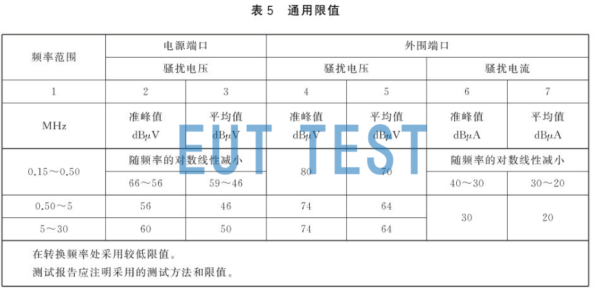 GB4343.1-2024 Emission limits for conducted nuisance at the power port and peripheral port 4.3.3.7 Wired network ports Wired network ports should meet the requirements of GB/T9254.1-2021, as well as the applicable harassment limits for Class B equipment in the frequency range of 150kHz~30MHz. | Increased: 1) Peripheral port nuisance current limit 2) Wired network port limit requirements Verify that the EUT containswired network portIf you have a wired network port and have not conducted a wired network port test, you need to supplement the test. |
| 4.3.5 Frequency range 1 GHz-6 GHz 4.3.5.1 General provisions In the frequency range 1 GHz to 6 GHz, EUTs and peripherals containing active electronic circuits shall be evaluated on the basis of the highest clock frequency used within the EUT in accordance with the upper frequency limit specified in Table 10. | Increased frequency range1GHz-6GHz Radiated Harassmentlimit value requirement |
| 4.4.1 General principles Intermittent disturbances at power supply ports shall be evaluated using the limits in 4.4.2, taking into account general exclusions (see 4.1) and exceptions (see 5.4.3). NOTE: Examples of equipment excluded under 4.1 (second paragraph). (b) Switching of resistive loads at grid voltage crossings to produce intermittent disturbances not exceeding the continuous disturbance limit. Smooth control of inductive loads with frequency converters or variable speed drives (VSD). Automatically stops and does not produce any clicking sound during a complete program; for this type of equipment, it is not worthwhile to continue testing because it does not produce a clicking sound. The test equipment shall comply with the provisions of 5.1, in particular 5.1.7. See the appendix for further guidance. | Added examples of intermittent harassment exclusions |
| 5.1.5 Current probes The current probe shall comply with the provisions of 5.1 in GB/T6113.102-2018 5.1.9 Radiation emission test site The measuring apparatus, including the antenna and the test site, shall meet the relevant requirements of the test method selected in accordance with 4.3.2, 4.3.4.5 and 4.3.5 (if applicable). The test site shall be validated according to the measured distance between the selected EUT and antenna with reference to the applicable provisions of GB/T6113.104-2021. Common Mode Absorption Device (CMAD)Shall be constructed and verified in accordance with GB/T6113.104-2021 | Test equipment was added: |
| 5.2.1.1 Ungrounded non-hand-held equipment in operation Unless otherwise specified in Appendix A, the EUT shall be placed relative to the floor for its intended typical use. Desktop EUTs shall. -RGP (0.4 ⫽ 0.05) m from RGP with dimensions of at least 2mx2m; AMN (0.8 ⫽ 0.05) m from AMN; -RGP (0.4 ⫽ 0.05) m from AMN. Maintain a distance of at least 0.8 m from other earthed conductive surfaces. Placement shall be such that the RGP projects at least 0.5 m beyond the boundary of the equipment under test. The RGP shall be horizontal or vertical (see Figures 23 and 24); the AMN shall be connected to the RGP; however, if the RGP is vertical and connected to a horizontal ground plane (e.g., a shielded room), the AMN may be connected to a horizontal ground plane. Floor standing EUTs (see Figure 25) should. At a distance of (0.12 ± 0.04) m above a horizontal RGP with dimensions of at least 2mx2m; placed at a distance of (0.8 sts 0.05) m from the AMN. Maintain a distance of at least 0.8m from other grounded conductive surfaces; place in such a manner that the reference ground plane projects at least 0.5m beyond the boundary of the equipment under test. Note: Specific heights and associated tolerances (0.12 by 0.04) ensure better reproducibility. Supporting objects for supporting the EUT and components at the required height shall be made of non-conductive material. | conductive harassmentLayout and measurements have increased: 1) Margin of distance (2) Improve the instructions for using the simulator |
| The following requirements apply to equipment whose power plugs are equipped with, or are specified to be equipped with, passive EMI suppression components (e.g., capacitors, inductors) at the time of use. If the power plug of the EUT supplied for testing already has EMI suppression components installed, test the equipment as supplied, i.e. the power plug should be connected directly to the EUT port of the AMN. If the power plug of the EUT provided for testing is not fitted with EMI suppression components, these shall be installed and connected in accordance with the instructions for use. These instructions, as well as the type and rating of the components specified for use, shall be indicated in the test report. When EMI suppression components are integrated into the power plug, they shall be connected directly to the EUT port of the AMN. In either case, the power supply leads shall be connected by the most direct path between their point of connection to the EUT and the EUT port of the AMN. For equipment with plugs or connectors equipped with EMI suppression elements, the user's manual should contain the following information (or similar): WARNING: Replace the power plug or cord only with the type specified for this equipment. | The arrangement of leads on the EUT port is increased: (1) Test requirements for equipment whose power plugs are equipped or specified to be equipped with passive EMI suppression components when in use; 2) Wired network port test method; Verify the original report, whether the EUT is equipped with or specified in the use of passive EMI suppression components, whether in accordance with the requirements of the new version of the standard for terminal nuisance voltage test. If there is and not according to the new version of the standard requirements of the test, need to be in accordance with the new version of the standard requirements of the terminal nuisance voltage project layout and testing. |
| When using the nuisance current method, the probe should clamp the leads connected to the same port together to counteract the effects of differential mode currents. If these leads cannot be fitted to the current probe at the same time, they may be separated, but it is still necessary to ensure that the leads sending and returning current are clamped together. Each group of related leads should be identified so that they can be tested separately according to the measurement procedure described in 5.2.3.3. For voltage probe measurements, the peripheral equipment should be placed at a distance of (0.8 by 0.05) m from the EUT. If the length of the peripheral lead is less than 0.8 m, the peripheral equipment should be placed as far away from the EUT as possible. For current probe measurements, the current probe should be placed at a distance of (0.3 x 0.03) m from the test port. In this case, the peripheral equipment should be placed at a distance of (0.8 x 0.05) m from the current clamp (see Figure 24). Note: When using a current clamp, the distance between the EUT and AE is approximately 1.1m. | Conducted Nuisance Increased Current Probe Test Method |
| 5.3.4.1 General principles In addition to the layout requirements specified in 5.3.4.3, the measurement method used to measure radiated emissions from equipment enclosure ports shall conform to one of the relevant requirements of the following basic standards. -CISPR 16-2-3:2016+AMD1:2019,If the test is conducted using an open air test site (OATS), semi airwave darkroom (SAC), full airwave darkroom (FAR), or free space open air test site (FSOATS), all test sites are validated in accordance with GB/T6113.104-2021; GB/T17626.20-2014, if the test is conducted using an open air test site (OATS), semi airwave darkroom (SAC), full airwave darkroom (FAR) or free space open air test site (FSOATS); GB/T17626.20-2014, if the test is conducted using a full airwave darkroom (FAR) or free space darkroom (FSOATS); GB/ T17626.20-2014, if the test usesTransverse electromagnetic (TEM) waveguideConduct. | Increased radiation nuisance: (1) Nuisance power test requirements for power plugs containing EMI filter components; (2) 30MHz ~1000MHz radiated nuisance test method; (3) 1GHz ~6GHz Radiated Nuisance Test Methods Verify the original report, whether the EUT is equipped with or specified to be equipped with passive EMI suppression components when in use, and whether the nuisance power test is conducted in accordance with the requirements of the new version of the standard. If there is and not according to the new version of the standard requirements of the test, need to be in accordance with the new version of the standard requirements of the nuisance power project layout and testing. |
| 5.4.2.2 Observation time Under the operating conditions specified in this document, the observation time T shall be determined only at 150 kHz and 500 kHz The following procedure shall be used to determine the minimum observation time. If the EUT is not run under program control, the minimum observation time is the shorter of the following: a) The number of minutes to count 40 clicks on one of the two frequency points; or e120 min. If the EUT does run according to the program, the minimum observation time is the duration of the full program if the click rate obtained from the full program is less than or equal to 0.5 and the program duration b) is greater than 20 min. Otherwise. The sum of the durations of the minimum number of complete programs required to count 40 clicks on one of the two frequency points; or If 40 clicks were not recorded 120 min after the start of the test, the sum of the durations of the minimum number of complete programs exceeding 120 min. Note 1:b) gives an explanation of the additional conditions N ≤ 0.5 and T > 20 min, and Appendix C gives an example of determining the minimum observation time. If the click rate is determined by counting the number of switching operations instead of the number of clicks, the same procedure shall be used. When case b) applies, the interval between the end of one program and the manual start of the next program shall be excluded from the minimum observation time. | Modified test methodology for intermittent nuisance test Verification of the original report requires retesting of the intermittent nuisance item, except for the apparatus for which the original report used the number of switching operations to determine the clicking rate and the apparatus excluded by example 4.4.1. |
| 6.2.1 During the test, the EUT shall be operated at the rated voltage specified for the equipment. For single-phase equipment with rated voltages in the following ranges. -100V~127V, the test shall be carried out at one of the nominal voltages within the range, the recommended test voltage being 120V. -200V~240V, the test shall be carried out at one of the nominal voltages within the range, the recommended test voltage being 230V. -100V~240V, the test shall be conducted at one nominal voltage within the range of 100V~127V or one nominal voltage within the range of 200V~240V, except that the user of this document may test the equipment twice, once at one nominal voltage within the range of 100V~127V and once at one nominal voltage within the range of 200V~240V, and this decision shall be documented in the test report. The decision shall be recorded in the test report. Where applicable, the above requirements also apply to the AC power port of the EPS. Multiphase equipment shall be tested using the same principles as described above for three-phase equipment with rated voltages in the following ranges. 200V~240V, the test shall be carried out at one of the nominal voltages within this range: the recommended test voltage is 220V. 380V~450V, the test should be carried out at one of the nominal voltages within this range: the recommended test voltage is 400V. 6.2.2 AC Power Port Frequency During the test, the EUT shall be operated at the rated frequency specified for the equipment. If the equipment has more than one rated frequency (e.g., 50 Hz to 60 Hz), the EUT shall be tested at only one of these frequencies. If the equipment has a rated frequency range (e.g., 50 Hz to 60 Hz), the EUT shall be tested at a frequency within that range. | Modified the selection method of test voltage and frequency. The new version of the standard requires no need to select the maximum harassment in the range of 0.9~1.1 times the voltage, and select a typical test voltage and frequency. |
| 6.3 DC power supply 6.3.1 Battery power When testing battery-powered EUTs, the type of battery used and its connection shall be as specified in the instructions for use. If the instructions specify the use of batteries of different ratings, it is preferable to use batteries of the largest capacity (e.g., Ah). A fully charged battery shall be used at the beginning of each test. During the test, the battery conditions shall be sufficient to maintain normal operating conditions. If the batteries are charged from an AC power source, the equipment shall be considered to be grid-powered in this mode of operation. 6.3.2 Non-battery powered DC supply During the test, the EUT shall be operated with typical power supplies at the rated voltage specified for the DC power supply unit. DC power supply equipment operating with a dedicated DC power supply unit (e.g., EPS) shall be tested in accordance with the DC power supply unit specified or recommended in the instructions for use. If a DC power supply unit is not specified or recommended in the instructions for use, or is not available at the time of testing, a typical power supply specified by the equipment to provide the rated voltage and current shall be used. The typical power supply selected shall be sufficient to meet the specifications of the EUT and shall meet the limits of this document when operated alone (see A.8.8 or A.8.9). The typical power supply used should be documented in the test report. | Increase: 1) Test requirements for battery powered equipment; (2) Test requirements for non-battery-powered DC equipment: It should be tested with a typical power supply that meets the requirements specified in the manual or configured in the laboratory. Verify in the original report that the EUT is powered by a DC power supply unit and that only the battery operating condition was tested without the DC power supply unit. If so, additional testing with a DC power supply unit is required. |
| 6.6 Equipment with built-in luminaires Unless otherwise specified herein, equipment with a lighting function shall be tested under the operating conditions specified in Appendix A with the lighting function at its maximum setting. If the equipment meets all the requirements of this document, 6.5 does not apply to the lighting function. Alternatively, if the lighting function of such equipment can be tested separately, the lighting function can be tested in accordance with the requirements of GB/T17743, and the rest of the equipment functions are tested in accordance with this document, and the lighting function is not activated. If the lighting function is not intended to be turned on continuously during normal operation, it is not necessary to test the lighting function. Note: A range hood is an example of a product whose lighting function can be turned on continuously during normal operation. A refrigerator is an example of a product whose lighting function is not intended to be turned on continuously during normal operation because the lights are off when the door is closed. | Addition of test requirements for built-in luminaire equipment EUT contains "can continuously turn on the lighting function during operation", and did not pass the GB/T17743 test, you need to turn on the lighting during the test to supplement all the test items. |
| 6.7 Devices that include IPT functionality The provisions of A.10 shall apply to the mode of operation during TPT start-up. When this is done, functions that are not powered by energy obtained from the IPT may be switched off and tested separately. Note 1: For example, the display portion of the IPT charging cradle can be powered directly from the grid rather than through the IPT power circuit. NOTE 2: Examples of functions that may be tested individually are: display sections on IPT charging cradles that can be turned off by the user or automatically by the equipment, or accessories that can be removed by the user In addition to the provisions in A.10, the normal provisions shall apply to the IPT in its unactivated mode of operation. NOTE 3: For example, massage equipment may be charged using a dedicated IPT charging cradle (operation mode 1, see case 3 of A.10) and used when IPT charging is stopped (operation mode 2. See A.1.5). | Addition of test methods for devices that include IPT functionality Verify that equipment with IPT capability has been tested, and if not, additional testing is required. |
| 8 Measurement uncertainty If guidelines for the calculation of uncertainty of measurement equipment and facilities are specified in GB/T6113.402-2018, they shall be followed. For these measurements, the uncertainty of the measuring instruments shall be considered in accordance with GB/T6113.402-2018 when determining whether the limits of this document are met. Where the test laboratory uncertainty is greater than the Uasp value given in GB/T6113.402-2018, the calculations required to determine the measurement results and any adjustments to the test results shall be included in the test report. | Refinement of the instructions for the use of uncertainty |
| 9 Test Reports Sufficient detail should be provided to facilitate the reproducibility of the measurements. Therefore, the test report should include: a description of the EUT. Information on the peripheral and auxiliary equipment used and their coupling to the EUT. During each type of measurement, a description of the mode of operation of the test and the settings to be used (e.g. control set to position 3): the test port and a description of its use (if applicable). Any special measures taken to ensure conformity (e.g. use of shielded cables); photographs of the measuring arrangement. Information on the components of the measurement system and their location (e.g., antenna distance, distance from the EUT to the reference ground plane). The EMC characteristics evaluated, the measurement methods used and the limits applied; the measured values obtained in accordance with the procedure detailed in 5.4. -Maximum clock frequency F within the EUT (see 3.9.1). In addition, the test report may include. -The margin between each value and the limit value. Information on measurement uncertainty in laboratories and how it is taken into account (see Chapter 8). | Addition of test report requirements |
| A.1 Electrically powered equipment for domestic and similar uses (former 7.3.1) A.2 Power tools (former 7.3.2) A.3 Electrically powered medical devices (formerly 7.3.3) A.4 Electrically heated equipment (former 7.3.4) A.5 Thermostats (former 7.2.4 to 7.2.5) A.6 Vending machines, amusement rides and similar equipment (originally 7.3.5) A.7 Electrical toys (former 7.3.6) A.8 Other equipment (add A.8.6 Air purifiers, A.8.9 External power supply, A.8.11 Robotic equipment, etc.) A.9 Induction cookware A.10 Appliances, other than induction stoves, using inductive power transfer (IPT) A.11 Operating conditions for specific equipment and integrated components | (1) Revised and improved the operating conditions of some products; (2) Increased operating conditions for some products, such as air purifiers and external power supplies |
| A.1.9 Refrigerated and freezer boxes Refrigerator and freezer should be closed for continuous operation. The thermostat is adjusted to the middle of the adjustment range. The box should be empty and unheated Measurements should be made after it has reached a steady state. The light inside the chamber shall be turned off during measurements, unless the light can be turned on by the user with the door closed or can be turned on continuously during normal operation. Note 1:The light in the wine cooler with glass doors is an example of a continuously on light. If the click is not measured, the click rate N is determined as half the number of switching operations. NOTE 2: Due to ice buildup on cooling elements, the number of switching operations in normal use is approximately half that of an empty refrigerator. | The new version of the refrigerator and freezer clearly states that "those that can be operated with the light on should be tested with the light on". |
| A.1.20 Air regulators A.1.20.1 If the temperature of the air is controlled by varying the interval between compressor runs in the appliance, or if the appliance has a heater controlled by a thermostat, the measurements shall be made under the same operating conditions as specified in A.4.14. A.1.20.2 If the appliance is in the variable capacity mode with inverter circuits controlling the speed of the fan or the compressor, the measurement is made with the thermostat set at the lowest temperature in the cooling mode and at the highest temperature in the heating mode. A.1.20.3 For equipment tested in accordance with A.1.20.1 and A.1.20.2, the ambient temperature shall be (15 ½) °C when the equipment is operated in the heating mode and (30 ½) °C when the equipment is operated in the cooling mode. If it is impractical to maintain the ambient temperature within this range, other temperature ranges are permissible as long as the equipment can be operated in a steady state. Ambient temperature is defined as the temperature of the air flowing to the indoor unit. A.1.20.4 If the appliance consists of an indoor unit and an outdoor unit (split type), the length of the connecting refrigeration tube shall be (5±0.3) m and shall be coiled, if possible, into a loop of approximately (1±0.3) m in diameter. If the length of the connecting tube cannot be adjusted, the connecting tube shall be longer than 4 m, but not longer than 8 m. For indoor and outdoor unit connection line nuisance power measurement, the connection line should be separated from the cooling tube and extended to meet the absorption clamp measurement. For other nuisance power and nuisance voltage measurements, the connecting wires of the two parts shall be arranged along the refrigeration tubes. When there is a requirement for a ground wire that is not part of the power lead, the earth terminal of the outdoor unit shall be connected to a reference earth (see 5.2.1, 5.2.2 and 5.2.3). For nuisance voltage measurements, the AMN shall be placed at a distance of 0.8 m from the unit (indoor unit or outdoor unit) connected to the AC power grid or, for nuisance voltage or nuisance power measurements, the test arrangement in A.1.20.5 may also be used. For the purpose of determining the starting frequency of the nuisance voltage or nuisance current test at ports other than the AC power port, if the length of the connecting leads is not specified in the instructions for use, it shall be assumed that the length of the leads is always greater than 2 m, but less than 30 m. NOTE: Due to limitations in the range of refrigerant tubes, the length of the connecting leads is always expected to be less than 30 m. | Air conditioner increase: 2) Radiated nuisance test method |
| A.1.10 The washing machine should be operated with water but without fabric, and the temperature of the incoming water should be in accordance with the instructions for use. Continuous harassment was evaluated only during the normal washing mode of cotton fabrics and during the spinning mode at maximum speed. For the assessment of continuous harassment, infrequent short-term events are not considered if they do not last more than a few seconds, e.g., during the beginning of the dewatering cycle. For the assessment of intermittent nuisance, if there is a 60°C washing program for cotton fabrics without pre-wash, measurements are made using the full program: otherwise measurements are made using the regular washing program without pre-wash. NOTE: If there is a washer with a dryer function as part of the overall program, see A.1.12 or A.1.13. (a) water leakage protection valves are not peripheral devices within the meaning of this document and measurements on the leads of these valves are not required. In the nuisance power measurement of the power supply lead, the water leakage protection hose shall be connected to the faucet, with a length of (0.4±0.05) m and the power supply lead arranged in parallel, with a maximum distance of 0.1 m. Then the power supply lead shall be measured according to the requirements of 5.3.3.2. | New version clarifies the EUT operating status of continuous and intermittent nuisance in washing machines |
| A.1.1 Vacuum cleaners A.1.1.1 Vacuum cleaners shall be measured in continuous operation without accessories and with an empty dust bag. Vacuum cleaners with power lead reels shall be measured with the power leads pulled out completely and arranged in accordance with 5.2.2.1. A.1.1.2 Measurements of nuisance voltage and nuisance current do not apply to leads integrated in the vacuum hose (see 4.3.3.3). A.1.1.3 If applicable, in addition to measurements of the power supply leads, nuisance power measurements shall be made on leads integrated in the vacuum hose if the plugs or sockets on the leads are readily replaceable by the user. The measurement shall be made by replacing the vacuum hose and its integrated lead with a cable of the necessary length to be connected to the terminals on the main unit and with the same number of wires as in the originally fitted vacuum hose.A.1.1.4 The power nozzle of the vacuum cleaner shall be operated continuously without mechanical loading of the brushes. If required, cooling shall be provided without unduly affecting the test results. The required cooling airflow shall be achieved without metal fixtures in the vicinity of the nozzle. If the powered nozzles are connected by non-extendable power leads with an overall length shorter than 0.4 m, or if they are connected directly to the vacuum cleaner by plugs and sockets, they shall be measured together. In all other cases, the EUT shall be measured separately. .... | Adding layout requirements for vacuum cleaner radiated emission measurements Verification of the original report, the vacuum cleaner was tested for radiated nuisance and was not arranged in accordance with the requirements of the new version, it is necessary to supplement the radiated nuisance test in accordance with the requirements of the new version of the standard. |
| A.4.11 Clothing irons The iron shall be operated with the soleplate cooled with air, water or oil. The heating control shall be set at the maximum temperature at (50 s.10)% duty cycle. The clicking rate N may be determined by the number of switching operations (f = 0.66 in Table B.1). Clothing irons that do not produce steam should be placed on a three-point pointed metal support at least 100 mm high, with the soleplate in a horizontal position, and cooled by air-cooling. The heating control should be set to the middle of the maximum temperature range available on the iron. Note: For an example of a metal support see IEC 60335-2-3:2012, 11.2. Clothing irons with a steam function should be set on the same stand as above for irons without a steam function. No additional cooling is required. The steam function should be switched on. In particular. -For irons capable of providing continuous steam, the steam control shall be set for continuous steam; for irons capable of providing steam injection, the steam control shall be set for continuous steam, if available, or for steam injection at a rate of one minute. The jetting operation is performed in a rhythm of 3 times. The test report should detail the settings selected for the test. Clothing irons can be rated for clicking using Appendix B. | Added description of the arrangement and EUT status during iron testing |
| As an alternative to counting the number of switching operations, for all devices in this table, the clicking rate can be determined by measuring the clicking sound. In this case, the factor f does not apply | The original switch operation number assessment of the equipment, the new version of the standard with the switch operation number and the number of clicking sound assessment can be |
| Appendix C General Provisions Intermittent nuisance is a transient nuisance with broadband characteristics, usually generated by switching operations. The effect of the harassment depends not only on the amplitude of the clicks, but also on the duration, spacing and repetition rate of the clicks. Since the amplitude and duration of individual clicks are not constant, a specific statistical evaluation method was developed in order to test the necessary reproducibility of the results. Intermittent disturbances are considered to cause less interference than continuous disturbances of the same amplitude, and therefore the limits for such disturbances have been relaxed in this document. | Addition of background information on intermittent harassment testing programs |
| Appendix D GENERAL PROVISIONS The CISPR limits are based on the recommendation that for type-approved equipment, it is desirable that the batch should comply with the limits at least 801 TP3T with a statistical base confidence level of at least 801 TP3T. The CISPR limits are based on statistical methods to take into account the actual and inherent variability of EMC performance of high-volume equipment Type tests are generally performed on a representative sample prior to mass production and sale. Therefore, it is appropriate for the type test to. In at least 3 samples according to one of the methods given below: or a) For simplicity, this was done on one sample only. b) For the assessment of intermittent harassment, option b) is preferred. It is desirable to carry out random follow-up testing of equipment in production from time to time, especially if option b) above is followed. | The old version of the standard was chapter 8 of the main text. The new version of the standard turns the method into an informative appendix. Failure to act as a request for enforcement |