Introduction:
This paper mainly introduces the importance of electrical isolation in modern electronic design starting from the effect of different sizes of current on the human body, and introduces in detail the four isolation methods of electrical isolation such as magnetic isolation, capacitive isolation, optical isolation, and digital isolator.
Why should I be concerned about hazardous currents?
The figure below shows the adverse effects that can occur when the human body is exposed to different sizes of current. It can be seen that as the current that invades the human body gets higher and higher, the human body will show different manifestations, including increasingly adverse effects ranging from vision, inability to get away from the energized conductor, and pain. In some medical systems, a current of 80 μA is also capable of causing harm to a patient, and the acceptable safe current limit is only 10 μA.
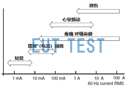
Effects of different currents on the human body
How can I reduce the likelihood of users being harmed by dangerous currents?
In order to avoid the effects of dangerous voltages, we often use isolation devices for electrical isolation in circuit design, and here is a look at four different types of isolation.
Magnetic isolation
Magnetic isolation is an electrical isolation method used for the longest time, coupling voltage signals through the body of a huge magnetic field coil, we are now common isolation power supply is the use of magnetic isolation isolation, its disadvantage is that the isolator volume is very large, occupies a lot of space, and only applies to the current power supply, generally used for high-power AC output use.
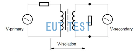
Electrical isolation schematic with magnetic isolation
Capacitive isolation - capacitive coupling
There is another type of electrical isolation is capacitive isolation is also known as capacitive coupling, its advantage is that the switching speed is very fast, and the size of the isolator can be grouped very small, but this type of isolation is very weak with the load capacity, the energy coupling efficiency is very low, so it is generally used only for isolation of hundreds of volts of voltage.
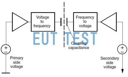
Electrical isolation schematic with capacitive isolation
optical isolation
Optical isolation is now the most commonly used method of electrical isolation, the market offers optical isolation devices to provide a very high electrical isolation value, isolation voltage up to 8000V, compared to the previous types of isolation, optical isolation can be said to be the highest level in the industry, optical isolation devices can be done in a very small package and high-speed communication, and can play a role of isolation for both AC and DC.
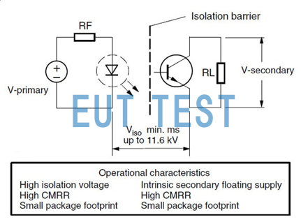
Schematic diagram of electrical isolation with optical isolation
Digital Isolator:
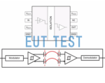
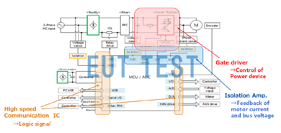
The operating principle of the digital isolator is shown below. The high speed communication IC is mainly used for communication signals between the controller and the peripheral current. The gate driver is used to control the gate of the power device. In addition, the isolation amplifier monitors each voltage and current and transmits them to the controller.
Isolation using digital isolators
A comparison table of optocouplers and digital isolators is shown below.
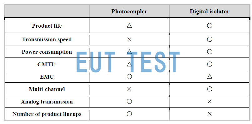
Comparison of Optocouplers and Digital Isolators
The digital isolator has the advantages of long barrier life, fast communication speed, high common-mode noise robustness, and low current consumption. In addition, it is easy to build multi-channel structures, thus reducing the number of parts.
Depending on the purpose of signal propagation, digital isolator products are divided into three main sections:
- High-speed communication IC: Transmits high-speed digital signals through an isolation barrier.
- Gate Driver: A driver IC that converts control signals from an external controller IC into control signals for a power device (MOSFET, IGBT, SiC, GaN).
- Isolation Amplifier: An amplifier that converts an input analog signal to a digital signal on the transmitter side and outputs an analog signal or a digital signal according to the output specifications.
Summary:
If you need to use digital isolators in your design, follow the resources below to learn how to choose the right digital isolator product: