
Introduction:
When we use EUTTEST to build the EMC test system in the process of EMC testing of EUTs, the reference ground plane located on the floor or wall of the test lab is an important reference point, good reference grounding of EMC test equipment can also ensure the accuracy and repeatability of EMC measurements, which provides all the test instrumentation and equipment in the entire EMC test system with A common zero potential. When all equipment ground ports are connected to this reference ground, it can ensure the normal loading of some synchronous signals or asynchronous signals, and can also reduce the EMC test system noise interference and affect the reliability of the test results.
Connection with reference to the ground plane
There are several common reference ground connections used when performing EMC testing:
Single point grounding:
Single point grounding is the connection of all equipment to ground through a common ground point. This is simple and easy to use and is suitable for testing small or low power devices. However, in high power devices or complex systems, single point grounding may result in changes in ground potential that can affect signal transmission and measurement results. Therefore, when using single-point grounding, its suitability needs to be carefully evaluated.
Single point earthing is widely used outside the laboratory as EUTTEST will place all EMC test instruments inside a cabinet, all instrumentation is connected to the cabinet surface via short connecting wires and then the cabinet is connected via metal screws at the bottom to an earth reference plane on the floor to complete the single point earthing.

Single point grounding of EMC test systems and equipment through cabinets
Multi-point grounding:
Multi-point grounding refers to the simultaneous connection of multiple grounding points to the equipment. This method can effectively reduce the ground potential difference and enhance the anti-interference capability of the system. However, care needs to be taken when designing to avoid the formation of ground loops that could introduce additional interference.
Multi-point grounding is the most commonly used connection in the EMC test system, because a system will have a lot of equipment as shown in the figure below, our transmitting antenna through the coaxial cable directly grounded, the EUT has two ways of floor-standing equipment and desktop equipment, the desktop equipment itself is not grounded, so we do not test the grounding, and for the floor-standing equipment, we need to be connected to the EUT directly underneath the Another grounding point, the different grounding methods of these test instruments in the darkroom for the grounding reference plane of the radio darkroom is a multi-point grounding method.
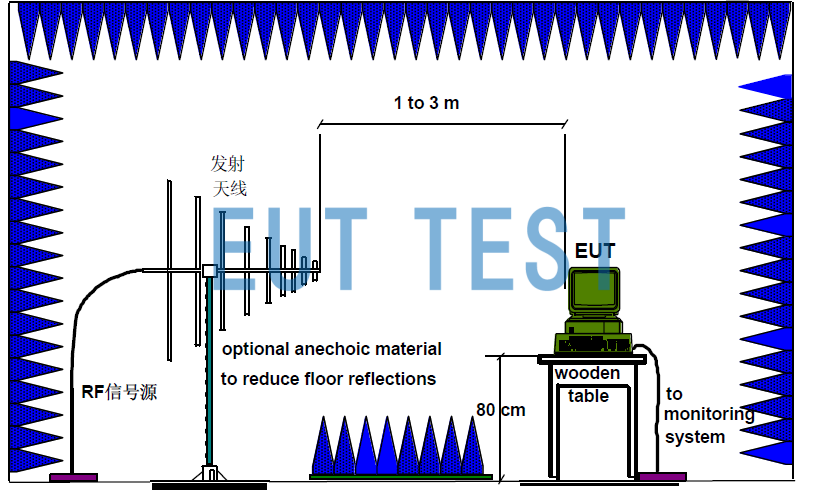
Transmitting antenna and DUT EUT are grounded by multi-point grounding.
Shield grounding:
In high-frequency circuits, shielding ground is an effective connection. The shielding material is usually connected to ground to form a protective layer to isolate external electromagnetic interference. In this way, signal integrity can be effectively improved to ensure measurement accuracy.
Principles for connecting the reference earth of EMC test equipment:
The procedure for connecting the reference ground should follow the following principles when performing equipment testing:
Determine the reference ground plane:
Before we start the connection, we should first contact Shenzhen EYT to set up the EMC test system. Whether it is a conductive test or a radiated test for EMC, we have to determine a reference grounding plane in the laboratory. The reference ground plane should be selected in the low noise area of the laboratory, and the grounding should at least meet the requirements of CNAS CL16, such as grounding resistance less than 1Ω and other requirements.
Use a short ground wire:
When connecting the reference ground, a short ground wire should be used as far as possible to connect the test instrument and the reference ground plane, in order to reduce the influence of the impedance and distribution parameters of the cable, and to minimize the conducted and coupled interference in signal transmission.
Attach to the bottom of the unit or to the chassis:
In many cases, the bottom of the unit or the enclosure can be used as a good reference ground connection point. This will reduce the length of the ground wire and improve the effectiveness of the grounding. If the equipment does not provide a reference ground point, grounding copper or copper foil tape can be used to affix to the exposed metal enclosure of the test instrument, and then connected to the laboratory ground reference plane using a shorter ground wire as described above.
Test the ground connection:
After connecting all the test instruments and cabinets to the reference ground plane, test the validity of the ground connection using a multimeter, ground resistance meter, and other tools to ensure the validity of the ground connection, and also to measure the ground resistance to see if it is within a reasonable range.
Considerations for EMC test equipment reference ground connections:
Current carrying capacity:
Ensure that the conductor connected to the reference ground has sufficient current-carrying capacity. You should know the operating current and voltage of the sample under test, then know the operating voltage and current of all EMC test equipment, and then take a maximum value as the current-carrying capacity requirement of the grounding cable to configure the grounding cable in order to avoid overheating and damage to the grounding cable.
Selection of grounding materials:
The use of highly conductive materials as grounding wire, usually copper or tinned copper is the preferred material, generally EUTTEST will be configured for the customer free of charge some pure copper grounding copper braid, and for the customer to play a good connection hole, and as a consumable configuration for the customer to use.
Prevents corrosion:
In humid or corrosive environments, we consider corrosion and rust protection for ground connection cables for our customers' EMC test systems to ensure long-term reliability.
Regular inspections:
The EMC test system built by our company will be accompanied by an after-sales instruction document, which is convenient for customers to understand the entireEMC Test SystemsStability and even components such as grounding cables are checked and maintained to ensure that they are always in good working condition.
Post-test data analysis:
After completing the EMC test and connecting the reference earth plane, it is very important to collect and analyze the test data. The accuracy of the data is highly dependent on the quality of the connection to the reference earth. Therefore, when analyzing the data, special attention needs to be paid to abnormal results that may be caused by grounding problems.EUTTEST has more than ten years of experience in installing and commissioning on-site EMC test systems, and can quickly troubleshoot some of the anomalies that can be caused by laboratory grounding.
Summary:
In the electromagnetic compatibility equipment test system test equipment and systems for reference ground connection directly affects the reliability and validity of the test results.EUTTEST through the reasonable grounding design, appropriate connection method of strict control, can significantly improve the customer's entire laboratory test system and equipment electromagnetic compatibility and stability. With the expansion of the laboratory test project demand, to a different brand of test equipment after the increase in the importance of the reference ground connection is more and more prominent, so all EMC testers can be through this article in-depth understanding of the reference ground connection method, to ensure that the EMC test equipment in the complex electromagnetic environment has an important significance to the normal operation of the work.