: 2017-01 Certification Test Program Overview")
Introduction:
The DIN V VDE V 0884-11 standard is the German certification standard for all digital isolators that are not optically isolated, and is used by major digital isolator manufacturers such as TI, TOSHIBA, etc. for certification testing.
The component standard VDE 0884-11 gives the terminology, basic ratings, characteristics, safety tests and measurement methods for both magnetic and capacitive couplers in digital isolators. Magnetic and capacitive couplers consist of a transmitter stage and a receiver stage on either side of a current-insulated gate. The device transmits signals across the insulating boundary, and the receiver stage is capable of detecting the transmitted signal and using that information to produce an electrical output signal. This standard specifies magnetic and capacitive barrier mechanisms as well as basic and reinforced insulation insulation functions. The following diagrams show the construction of two magnetic and capacitive isolators and the test standards are DIN V VDE V 0884-11 and UL 1577.
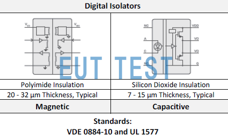
DIN V VDE V 0884-11 and UL 1577 Testable Products - Digital Isolators
For optoisolators, use the standard test test shown below. Refer to other documents for more information.
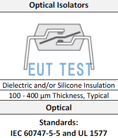
IEC 60747-5-5 and UL 1577 Testing Optocouplers - Optoisolators
DIN V VDE V 0884-11 (VDE V 0884-11): 2017-01 Test item
The following table summarizes the test items for a particular digital isolator for certification to VDE V 0884-11.
For details of the test equipment required for each test item see: Digital Isolators - High Voltage Enhanced Isolation: Safety Regulations, Standard Definitions and Test Methods
<<<<提醒:左右滑动表格>>>>| Test items | Test Item Name | Test Specification Requirements | (be) worth | unit (of measure) |
| Maximum repetitive peak isolation voltage Maximum Repeated Peak Isolation Voltage (EUTTEST provides the instrumentation required for testing) | AC voltage (bipolar) AC Voltage Bipolar | 2121 | ||
| Maximum working isolation voltage Maximum operating isolation voltage (EUTTEST provides the instrumentation required for testing) | AC voltage (sine wave); time dependent dielectric breakdown (TDDB), AC Voltage (sine wave) | 1500 | ||
| DC voltage DC voltage | 2121 | |||
| Maximum transient isolation voltage Maximum transient isolation voltage (EUTTEST provides the instrumentation required for testing) | =, t = 60 sec (qualification) = 1.2 × , t = 1 s (100% production) | 8000 | ||
| Maximum surge isolation voltage Maximum surge isolation voltage (EUTTEST provides the instrumentation required for testing) | Test method per IEC 62368-1, 1.2/50 μs waveform. = 1.6 × = 12800 (qualification) | 8000 | ||
| Apparent charge partial discharge (EUTTEST provides the instrumentation required for testing) | Method a, After Input/Output safety test subgroup 2/3. = , = 60s. (m) = 1.2 X = 2545 , = 10s | <5 | pC | |
| Method a, After environmental tests subgroup 1. = , = 60s. (m) = 1.6 X = 3394 , = 10s | <5 | pC | ||
| Method b1; At routine test (100% production) and preconditioning (type test) = 1.2 ×; = 1s. (m) = 1.875 * = 3977 , = 1s | <5 | pC |
The above tests require more than one instrument to complete the test, contact EUTTEST for more information.
(1) Creepage distance and electrical clearance requirements shall be based on the specific equipment isolation standard being applied. Care should be taken to maintain the circuit board design creepage distance and clearance distance to ensure that mounting pads for isolators on the printed circuit board do not shorten this distance. In some cases, the creepage distances and clearances on the printed circuit board become equal. Techniques such as inserting notches and/or ribs into the printed circuit board are used to help improve these specifications.
(2) This coupler is suitable for safe electrical insulation only within the safety class. Compliance with the safety class shall be ensured by means of appropriate protective circuitry.
(3) Testing in air or oil to determine the inherent surge immunity of the barrier.
(4) The apparent charge is a discharge caused by a partial discharge (pd).
A particular isolator chip was tested in certification testing for the following parameters and criteria:
- Safety-related certifications.
- 8000-VPK reinforced Isolation per DIN V VDE V 0884-11:2017-01
- 5.7-kVRMS isolation for 1 minute per UL 1577
- CSA certification per IEC 60950-1, IEC 62368-1, IEC 61010-1 and IEC 60601-1 end equipment standards
- CQC certification per GB4943.1-2011