Introduction:
TEMZ 5231 is a 50Ω ribbon cable manufactured by Schwarzbeck, Germany and authorized for sale by EUTTEST Shenzhen for evaluating the compliance of automotive electronic components with the ISO11452-5 test standard, and can be used for the immunity test in Appendix A.1 of the ISO11452-5 standard.
If you need to purchase 90Ω ribbon wire required by ISO11452-5, please purchase: TEMZ 5232 The
Bandwagon Profile:
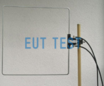
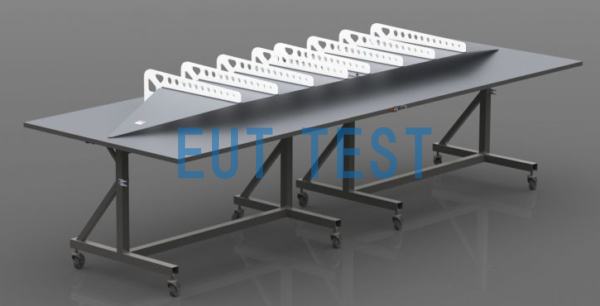
This is an open, asymmetrical 50 Ω ribbon cable for automotive immunity testing of automotive components. The strip line is supplied with a basic frame with casters (option).Foldaway Folding Table). If not in use, the ribbon line can be divided vertically into two parts. The banding base plate can be rotated vertically to save space. It takes only 5 minutes to get the ribbon line ready for use. The Ribbonline comes with an open access area to simplify the placement of test equipment.

Option Foldaway Folding Table

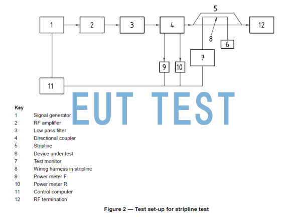
ISO 11452-5 Ribbon Line Test Configuration Chart
TEMZ 5231 ribbon cable is required for ISO 11452-5 ribbon cable testing and automotive electronics LISNs are also required, for details click on the link below or contact EUTTEST for more information on the equipment.
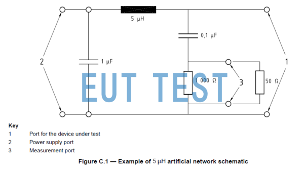
5μH Artificial Power Network

ISO 11452-5 Requirements for automotive electronic power supply network ANs
Uses of the strip line:
The asymmetrical 50 Ω ribbon line meets the requirements of ISO 11452-5. The stripline can be used to create maximum TEM waves. The field polarization distribution for TEM mode operation within the 220 MHz stripline is very uniform. The stripline can also be used above 220 MHz, in which case higher modes do exist, which provide their own characterization of the position-dependent fields. Unlike the TEM mode, in which the magnetic field force is smaller at the edge of the stripline and increases towards the center, the higher modes show the opposite characteristics: the field force is smaller at the center of the stripline and rises to a maximum at the edge of the strip conductor. During multi-mode operation, the direction is further optimized for changes in certain regions. When operating in TEM mode, the radiation and dielectric losses in the plastic support rods cause only small losses. Less than 1% of the incoming power is reflected back to the source due to minimized impedance mismatch. The dielectric and radiation losses at the TEM operating frequencies are as follows: |S21+ ± 0.5 dB, Loss: 11% |S21+ ± 1.0 dB, Loss: 21% |S21+ ± 1.5 dB, Loss: 29% Losses increase for multi-mode operation, with the output connector providing only 50% of feed at 380 MHz. At 800 MHz, only 25% is available, and at 1 GHz, the output connector provides only 12% of feed. The VUFM 1670 field meter of the VUFM 1671 LCD display unit is ideal for monitoring the actual field forces in the stripline, which is connected via a fiber optic link.
For the localization of the EuT it is recommended to use (almost) dielectric neutral materials, e.g. foams or polysilicon plastics. The suitability of the material can be checked as follows: measure the insertion loss of the empty cell, then place the tested material in the cell and measure the insertion loss again. The smallest difference in attenuation between empty and loaded cells indicates a suitable material. The EuT of the device being tested should be placed in the center of the strip. It is recommended that the EuT position be recorded as accurately as possible for repeatability of the test.
Technical parameters:
<<<<提醒:左右滑动表格>>>>| Model number | TEMZ 5231 |
| manufacturer | Schwarzbeck |
| agent | Euttest |
| Device name | Automotive Electronic Strip Line Test System |
| Nominal frequency range TEM mode | DC-220MHz |
| usable range TEM or higher mode | DC-1GHz |
| Nominal Impedance | 50Ω |
| SWR | < 1.5 (f < 220 MHz) 220 MHz) |
| Voltage Field Strength Conversion | 1 V = 6.67 V/m 1 V/m = 0.15 V |
| Maximum input power | 1kW Short time 500W continuous |
| size | 740*150*2500mm |
| quality | 166kg |
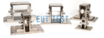
Option list:
Opt. Termination 150 W: 50 Ohm Termination, N Jack, 150 Watts
Opt. Termination 500 W:50 Ohm Termination, N-Type Jack, 500 Watts
Opt. Foldaway. Side arms will be used instead of the cylindrical rods used to hold the diaphragm in place.The TEM-CELL can be folded up vertically. A stainless steel structure with casters supports the TEM. must be ordered with the ribbon cable, cannot be retrofitted
Curve diagrams of parameters related to technical parameters:

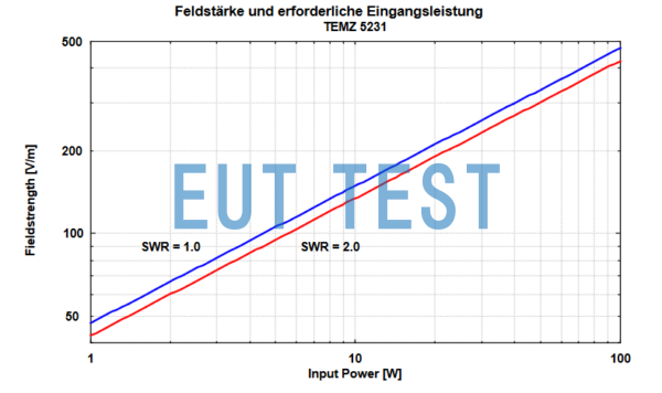
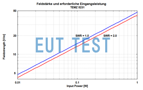
Input 1W power vs. output field strength

Input 100W power vs. output field strength 1W