Introduction:
The P1 set is a mini transient EMF generator set produced by Langer emv in Germany and authorized for sale by EUTTEST. The langer P1 set contains two magnetic field and one electric field injection type field source probes, which can be manually controlled to generate and stop the electric/magnetic field. Each probe has a range of action of only a few square millimeters, making it ideal for applying EMF interference directly to the surface of the PCB under test. Learn more about the product's technical parameters and how to use it below.
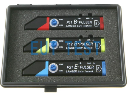
The P1 set Probe Combo Kit contains three different probes:
- P11 Transient Magnetic Field Interference Generator - for locating weak points or areas of magnetic field radiation in PCBs
- P12 Transient Magnetic Field Interference Generator - for locating more detailed locations in areas of weak radiation - cable/pins
- P21 Transient E-field Interference Generator - for locating weak points or areas of E-field radiation in PCBs
P1 Characteristics of the three probes:
- The probes are compact and can be applied directly to the GND / VCC / or signal line of interest of the PCB.
- Can apply interference to chip pins or peripheral circuits
- The strength of the electric or magnetic field can be adjusted manually.
- It is possible to distinguish whether PCBs are weaker to electric or magnetic field interference
Technical parameters:
<<<<提醒:左右滑动表格>>>>| Field Probe Model | P11 | P12 | P21 |
| Field Probe Name | Magnetic Field Transient Interference Generator | Magnetic Field Transient Interference Generator | Electric Field Transient Interference Generator |
| manufacturer | Langer emv | Langer emv | Langer emv |
| agent | Shenzhen EUTTEST | Shenzhen EUTTEST | Shenzhen EUTTEST |
| generated electric field strength | / | / | 100 kV/m |
| Density of magnetic flux generated | 1 mT | 1 mT | / |
| Field strength adjustment method | Manually adjustable | Manually adjustable | Manually adjustable |
| field generator Pulse Rise Time | 2ns - 8ns | 2ns - 8ns | 1.8ns - 10ns |
| field generator pulse frequency | Single / 5kHz | Single / 5kHz | Single / 5kHz |
| field generator Pulse Polarity | switchable | switchable | switchable |
| electricity supply | Battery 1.5V | Battery 1.5V | Battery 1.5V |
| Illustration of the role of field probes |  P11 Magnetic Field Transient Interference Generator Generates Beam Shaped Magnetic Field |  P11 Magnetic Field Transient Interference Generator Generating Ring Magnetic Field |  P21 Electric field transient generator generates vertical electric field |
Example of EMF sensitivity of an electronics module:
Module sensitivity:
- The denser the GND system in an area of the module, the less likely that area will be affected.
- If the module has a weak GND system (pulsers spaced 3 cm apart), the large surface area will usually respond to pulse interference.
- Weaknesses are concentrated in small areas of modules with strong grounding systems (placing the pulse generator on a surface).
- Signal rail loops with low ohmic drivers (standard outputs of digital ICs) are particularly sensitive to magnetic fields.
- High resistance signal line structures (quartz, pull-up resistors) are particularly susceptible to electric fields.
Single pulse:
These pulses are used to identify edge-sensitive signal lines and components, and a single pulse is usually enough to trigger a functional fault, such as the RESET pin of an IC or a component.
How to use P1 set:
The following two tests are required to search for radiation weak points on the PCB of an electronic product using the three probes of the P1 SET:
- First look for magnetic sensitivities and weak points (B Pulse generator/red P11 probe.)
- Then look for electric field sensitivities and weak points (E pulser/blue P21 probe).
Both tests were tested once each using the steps below.
Steps:
- Setting maximum intensity (MAX), pulse train 5 kHz
- Begin inspecting the surface of the EUT at approximately 5 cm intervals at a time.
- Hold the pulse generator vertically so that the front of the probe touches the surface of the DUT module under test.
- Switch polarity and repeat the process. Gradually approach the surface of the EUT and repeat the procedure.
- If a malfunction occurs, manually reduce the strength of the magnetic field generated by the probe.
- Weak points are identified by further approaching the module surface (track/assembly).
- If a functional malfunction has not yet occurred, place the pulse generator vertically on the surface of the EUT and inspect the surface. The highest level of resolution and interference can be achieved when the pulse generator is placed on the surface of the EUT (planar module) at the proper intensity setting.
Training Notes:
If you still have questions about this product, we will provide training instructions in Chinese or on-site training service after supplying the goods, contact us for more information.