Introduction:
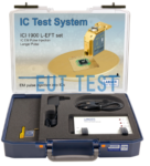
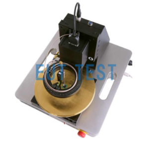
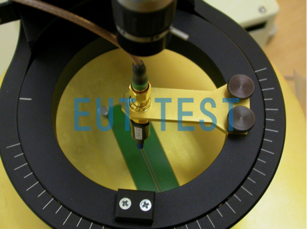
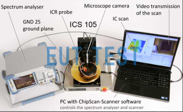
The ICS 105 set is an IC scanner test system manufactured by Langer - EMV, Germany and distributed by EUTTEST in Shenzhen, China. The ICS 105 set includes an ICS 105 for near-field, high-frequency, near-field measurements of small ICs ((50x50x50) mm spatial area) and small PCBs, with a spatial resolution of up to 50 μm, and with optional 1.5 MHz to GHz H-field and E-field probes for testing of CI ICs or small PCBs. Optional 1.5MHz to 6GHz H-field and E-field probes are available for testing CI ICs or small PCBs.

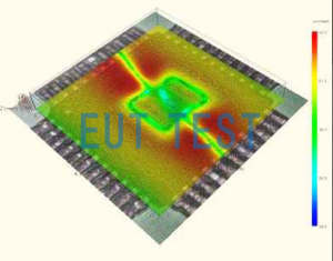
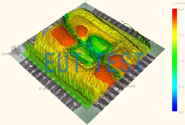
ICS 105 set system test chart
Shipping list:
- The ICS 105 set is an integrated circuit near-field scanning test system that contains the following components:
- 1x ICS 105 mainframe
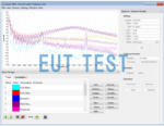
- 1x CS-Scanner, ChipScan-Scanner Software
- 1x GND 25, Ground plate according to IEC 61967
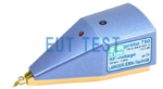
- 1x DM-CAM high resolution camera
- 1x ICS 105 acc Annex
- 1x ICS Flight case Box
Technical parameters:
<<<<提醒:左右滑动表格>>>>| Device supply voltage | 110V or 220V |
| computer communication port | USB |
| Maximum moving space | (X-axis x Y-axis x Z-axis) mm (50 x 50 x 50) mm / α-Rotation ±180° |
| Minimum Moving Space | (X-axis x Y-axis x Z-axis) mm (10 x 10 x 10) µm / α-Rotation 1° |
| travel speed | (X-axis x Y-axis x Z-axis) mm (2 x 2 x 2) mm/s / α-Rotation 45°/s |
| weight | 23kg |
| Size | 350 mmx 400mm x 420mm |
Optional accessories for ICS105 set
<<<<提醒:左右滑动表格>>>>| E-field probe | ICR E150 set Miniature Near Field Probe ICR E150: Available Frequencies 7 MHz - 3 GHz |
| H-field probe | Magnetic field probe; for use with ICS 105; ICR HH H Field (receives vertically oriented magnetic field lines); The "100" in HH100 represents the internal diameter of the probe tip (μ m). ICR HH H Field (receives perpendicularly oriented magnetic field lines) HH100 represents the internal diameter of the probe tip (μm); ICR HH100-27: Available frequencies 1.5 MHz - 6 GHz ICR HH100-6: Available frequencies 2.5 MHz - 6 GHz ICR HH150-27: Available frequencies 1.5 MHz - 6 GHz ICR HH150-6: Available frequencies 2.5 MHz - 6 GHz ICR HH250-6: Available frequencies 2.5 MHz - 6 GHz ICR HH250-75: Available frequencies 0.5 MHz - 2GHz ICR HH500-6: Available frequencies 2 MHz - 6 GHz ICR HH500-75: Available frequencies 200kHz - 1 GHz ICR HV H Field (receives horizontally oriented magnetic field lines) HV100 represents the internal diameter of the probe tip (μm); ICR HV100-27: Available frequencies 1.5 MHz - 6 GHz ICR HV100-6: Available frequencies 2.5 MHz - 6 GHz ICR HV150-27: Available frequencies 1.5 MHz - 6 GHz ICR HV150-6: Available frequencies 2.5 MHz - 6 GHz ICR HV250-6: Available frequencies 2.5 MHz - 6 GHz ICR HV250-75: Available frequencies 0.5 MHz - 2GHz ICR HV500-6: Available frequencies 2 MHz - 6 GHz ICR HV500-75: Available frequencies 200kHz - 1 GHz |
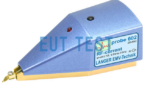
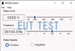
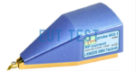
| Handheld Probes Contains electric and magnetic fields LFS sequence (<50MHz) RFS sequences (<3 GHz) XFS sequences (<6GHz) | Handheld probe; the handheld probe can be attached to the ICS 105 set of brackets or can be used handheldSequence I, LFS, Passive, 100 kHz up to 50 MHzLFS-B 3: 100 kHz up to 50 MHz Sequence II, RFS, Passive, 30 MHz up to 3 GHzThe RFS Scanning Probe Set consists of three passive near-field probes for scanning measurements of electric and magnetic fields in the research and development phase in the frequency range of 30 MHz to 3 GHz.The probes of the probe set enable measurements to be made close to the electronics module to locate the source of interfering signals. They record the entire graph of the near-electric and near-magnetic fields of the object under test. The scanning probe set is equipped with external chip current attenuation and electrical shielding. The scanning probes can be connected to the 50Ω input of a spectrum analyzer or oscilloscope. There is no 50Ω termination impedance inside the probe. The measurement signals of the scanning probes can be amplified by preamplifiers of type PA 203 or PA 303. RFS, LFS, SXS and XFS scanning probes are available on request. The different probes in the following RFS sequences all have different probe sizes and can be optionally or fully configured as required. RFS-R 50-1, Scanner Probe 30 MHz up to 3 GHzThe RFS-R 50-1 H-field probe is designed for taking field measurements on assemblies, devices or cables at a distance of up to approx. 3 cm. The H-field probe can be used to identify larger components as sources of interference. probe can be used to identify larger components as sources of interference. RFS-R 3-2, Scanner Probe 30 MHz up to 3 GHz RFS-R 0.3-3, Scanner Probe 30 MHz up to 3 GHzRFS-B 3-2, Scanner Probe 30 MHz up to 3 GHzThe measurement coil of the RFS-B 3-2 H-field probe is arranged orthogonally to the probe shaft. This allows the probe head to be positioned very close to the assembly and to achieve a strong coupling. This allows the probe head to be positioned very close to the assembly and to achieve a strong coupling. The RFS-B 3-2 detects magnetic field lines, which exit the measuring object othogonally. ... RFS-B 0.3-3, Scanner Probe 30 MHz up to 3 GHzRFS-E 02, Scanner Probe 30 MHz up to 3 GHzRFS-E 03, Scanner Probe 30 MHz up to 3 GHzUsing the approx. 4×4 mm electrode, which is located in the bottom of the RFS-E 03 probe head, E-fields from clocked lines, IC pins, and smaller components E-fields from clocked lines, IC pins, and smaller components can be detected. RFS-E 05, Scanner Probe 30 MHz up to 3 GHzRFS-E 10, Scanner Probe 30 MHz up to 3 GHzSequence III, XFS, Passive, 30 MHz - 6 GHzThe different probes in the XFS sequence below all have different probe sizes and can be optionally or fully configured as required. XFS-R 3-1, Scanner Probe 30 MHz up to 6 GHzThe XFS-R 3-1 near-field probe is designed for direct high-resolution measurements of RF magnetic fields on an assembly, e.g. around the pins and IC cases, conducting paths, decoupling capacitors, and EMC components. The XFS-R 3-1 near-field probe is designed for direct high-resolution measurements of RF magnetic fields on an assembly, e.g. around the pins and IC cases, conducting paths, decoupling capacitors, and EMC components. XFS-B 3-1, Scanner Probe 30 MHz up to 6 GHzThe measurement coil of the XFS-B 3-1 H-field probe is set at a 90° angle to the probe shaft. By positioning the probe head vertically, the measurement coil touches the surface of the printed circuit board directly. By positioning the probe head vertically, the measurement coil touches the surface of the printed circuit board directly. ... XFS-E 10, Scanner Probe 30 MHz up to 6 GHzThe electrode in the probe head of the XFS-E 10 has a width of approx. 0.2 mm. With the probe even smallest E-field sources can be located, e.g. conducting With the probe even smallest E-field sources can be located, e.g. conducting paths with a width of 0.1 mm or single pins on multi pinned ICs. To measure, the E-field probe is positioned onto the object. XFS-E 09s, Scanner Probe 30 MHz up to 6 GHzThe electrode on the probe head of the XFS-E 09 detects electrical fields which, for example are decoupled above the IC's surface. The probe's resolution allows for measurements with a distance of 0 5 mm to 10 mm above an assembly. 's resolution allows for measurements with a distance of 0.5 mm to 10 mm above an assembly. |