Introduction:
The concept of voltage probe comes from the EMC test standard CISPR16-1-2 and the description of section 5.2 in GB/T 6113.102. According to the CISPR16 standard or related product standards, all EUTs need to be tested for conducted emissions to prevent high-frequency interferences from being generated in the power line during normal operation of the electronic product and spreading out to interfere with other electronic devices. Conducted emissions are generally tested using LISN Linear Impedance Stabilization Network or artificial power network test, but some special occasions such as can not be connected to the LISN or there is no suitable LISN selection, then you can choose to test the voltage probe.
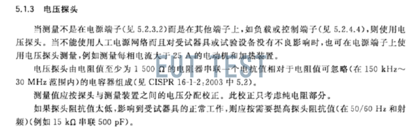
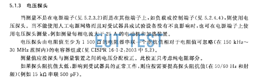
CISPR16-1-2 and GB/T 6113 are both basic standards. Some other product standards, such as Section 5.1.3 of GB 4343.1 (shown in the figure below), also specify the use of radiation CISPR16-1-2 high impedance voltage probe method for testing, the standard requires non-power supplyTerminals such as load and control terminals are tested with voltage probes instead of LISN.
The original description of the voltage probe in the CISPR16 standard
It should be noted that the CISPR16 standard actually states that the voltage probe can be used for testing power cords and even any cables, but when the product standard has special requirements, the test should first follow the requirements of the product standard.
Advantages of voltage probes over LISN:
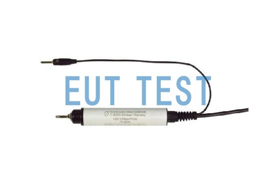
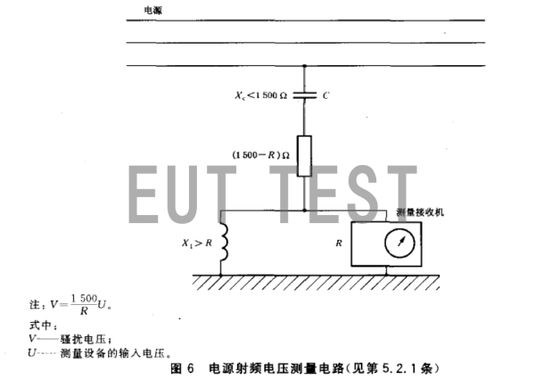
We use the commonly used TK9420 probe to illustrate the advantages of the voltage probe. The probe consists of a DC blocking capacitor C and a resistor of 1500Ω. The built-in resistor makes the resistance between the power cord and the bottom line of the EUT 1500Ω. The standard GBT 6113.102 and CISPR16-1-2 clearly give a high impedance.The structure and test principle of the voltage probe are shown in the figure below:
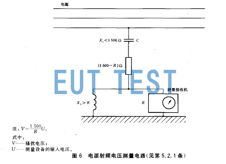
Structure and test schematic of voltage probe
The 1.5kW high-impedance voltage probe can be used for terminal conduction voltage emission measurement, and it is also used for CE evaluation of cables, output sockets, PCB traces, and test cables. In many cases, the operating circuit of some EUT requires high input impedance and low capacitance to reduce the impact on the EUT. The use of high-impedance voltage probes for external air conditioners, high-power electrical appliances, etc. can avoid complicated LISN cable wiring problems, because most LISNs are fixed input connectors. When the power interface of the EUT is relatively special, a special adapter needs to be customized for the EUT, which undoubtedly increases for third-party EMC laboratories, etc.The preparation time and consumption before the test.
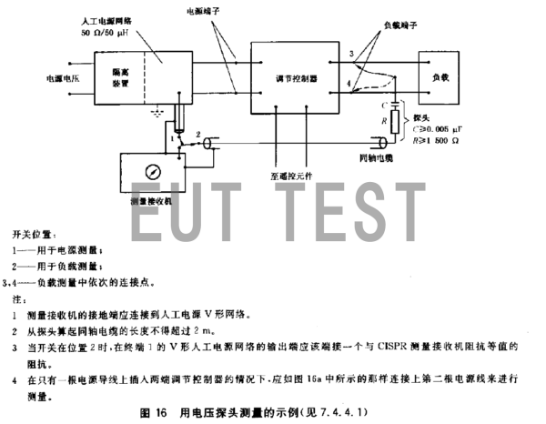
The power terminal and load terminal in the figure below are example diagrams of the two TK9420 test methods, showing the test method of the power terminal and the load terminal.

Test layout diagram using a voltage probe and LISN artificial power supply network
Standard requirements for the technical parameters of the voltage probe
- Within the specified frequency range, the probe should provide a high radio frequency impedance between its measurement point and the reference ground so as not to affect the voltage under test.
- The probe should have an isolation capacitor, the magnitude of which can ensure that the line voltage will not damage the measuring receiver.
- The probe should provide a specified 50Ω connection port (connector) to connect to a standard (CISPR) measurement receiver for specified harassment measurements.
- The probe should provide a specified connection so that the reference ground can be connected to the point in a specified manner through a specified maximum length of wire, unless the reference ground is required to be connected to the EUT in another specified manner.
- The probe should be calibrated in accordance with the prescribed procedures. At this time, the procedures should take into account parasitic effects near the measurement point, such as undesirable capacitive coupling between the measurement point and the shielding layer of the probe. The impedance of the probe and the input impedance of the measuring equipment should be independent of the frequency, otherwise it should be considered in the correction process.
- The nameplate of the probe should indicate the maximum value of the line voltage.
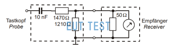
How to use a voltage probe to test CE:
The figure below is a test schematic diagram of the commonly used TK 9420 probe on the market. The dashed box on the left is the basic composition circuit of the probe, and the dashed box on the right is the receiver or spectrum analyzer. The probe on the left can be connected to the EUT cable to be tested, and then the ground terminal of the probe can be connected to the ground of the test laboratory. Many details need to be paid attention to during the actual test, otherwise some bypass capacitor problems will affect the test results, and relevant information will be provided in our company's after-sales technical consultation.
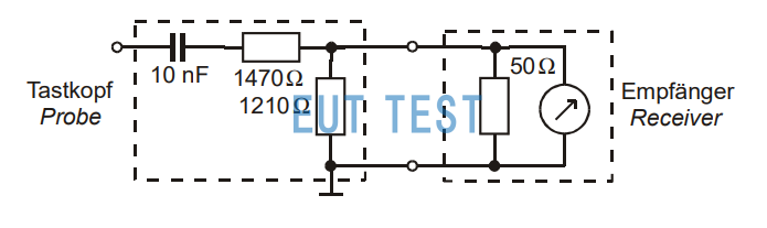
Test connection diagram of the voltage probe
In summary, the above and consideration of the structure of Schwarzbeck's TK 9420 show that TK 9420 is a device that meets the standard CISPR16 and can complete the conduction emission test of 150kHz-30MHz.
Recommended models of voltage probe equipment commonly used in laboratories:
The GERMAN SCHWARZBECK company has produced A variety OF models of voltage probes and authorized OUR COMPANY EUTTEST to sell them as an agent.
Highly resistive voltage probe:
For detailed technical parameters of each probe, please click the corresponding link below to view:
- TK 9420 Impedance 1.5 kΩ|4 pF at 10 kHz - 30 MHz - Voltage AC 2.5kV - DC 4.4kV (with VT 9420 voltage divider)
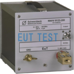
- TK 9421 Impedance 1.5 kΩ|4 pF, Frequency 9 kHz - 30 MHz - Voltage AC 10kV - DC 15kV
- TK 9422 Impedance 5 kΩ||4 pF at 9 kHz - 30 MHz - Voltage AC 10kV - DC 15KV
- TK 9261 Impedance >100 kΩ at 50 kHz - 700 MHz - Voltage AC 10Vp-p - DC 500V
- TK 9417, impedance 2.5 kW, frequency 10kHz–30 MHz,电流0.79mA@50Hz
Capacitive voltage probe:
F-CVP-1 FCC
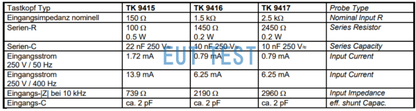
The following equipment has been discontinued:
- TK 9415 ,100Ω||22nF;
- TK 9416 ,1450Ω||10nF;
- TK 9417 ,2450Ω||10nF;
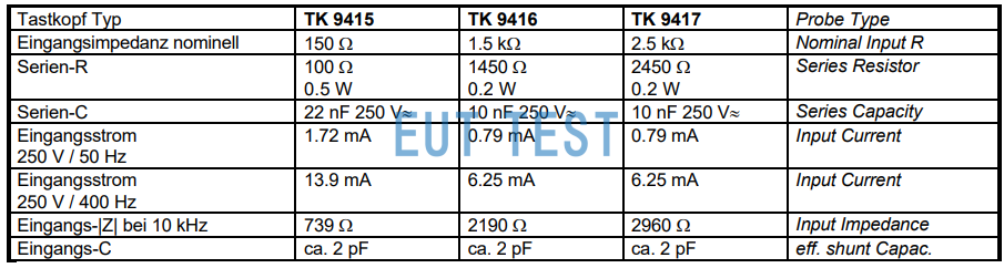
Schwarzbeck TK 9415 TK9416 TK 9417