Introduction:
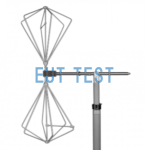
Typical applications for Helmholtz-Coils are in accordance with automotive standards ISO11452-8, SAE J551-17, MIL-STD-461F.Low Frequency Magnetic Field Immunity Test. Specifically designed to generate precisely defined magnetic fields in the upper end of the frequency range from DC to audio and beyond, the generated field is in a strong linear relationship with the coil current. Depending on the coil geometry, the number of turns and the coil current, the field strength can be precisely calculated analytically (or numerically).
Helmholtz-Coils are therefore ideally suited for the calibration of magnetic field probes or sensors, where the coil current is proportional to the magnetic field strength when the coil generates a magnetic field.
Selection:
The following table shows a collection of Helmholtz-Coils models manufactured by Schwarzbeck that EUTTEST represents and sells. If you are not sure which model to choose, you can contact EUTTEST for more information.
The CONTINUOUS in the table below represents the availability of contact work.
<<<<提醒:左右滑动表格>>>>| Model number | amps | field strength |
| HHS 5201-6 | 40 A (1 min.) 15 A (15 min.) 12 A continuous | 2860 A/m (1 min.) 860 A/m continuous |
| HHS 5201-98 | 40 A (1 min.) 15 A (15 min.) 12 A continuous | 64 kA/m (1 min.) 20 kA/m continuous |
| HHS 5202-9 | 55 A (5 min.) 33 A continuous | 3053 A/m (5 min.) 1832 A/m continuous |
| HHS 5202-81 | 6 A (5 min.) 5 A continuous | 3000 A/m (5 min.) 2000 A/m continuous |
| HHS 5204-12 | 60 A (5 min.) 30 A continuous | 2500 A/m (5 min.) 1288 A/m continuous |
| HHS 5204-36 | 20 A (5 min.) 10 A continuous | 2500 A/m (5 min.) 1288 A/m continuous |
| HHS 5206-8 | 55 A (5 min.) 34 A continuous | 1060 A/m (5 min.) 650 A/m continuous |
| HHS 5206-16 | 55 A (5 min.) 33 A continuous | 2100 A/m (5 min.) 1260 A/m continuous |
| HHS 5206-132 | 15 A (5 min.) 10 A continuous | 4713 A/m (5 min.) 3142 A/m continuous |
| HHS 5210-10 | 20 A (5 min.) 10 A continuous | 300 A/m (5 min.) 150 A/m continuous |
| HHS 5210-100 | 15 A (5 min.) 9 A continuous | 2183 A/m (5 min.) 1310 A/m continuous |
| hhs 5210-100 2.5 | 20 A (5 min.) 15 A continuous | 2900 A/m (5 min.) 1746 A/m continuous |
| HHS 5212-10 | 20 A (5 min.) 10 A continuous | 250 A/m (5 min.) 125 A/m continuous |
| HHS 5213-50 | 8 A (5 min.) 5 A continuous | 390 A/m (5 min.) 240 A/m continuos |
| HHS 5213-100 | 15 A (5 min.) 9 A continuous | 900.9 A/m continuos |
| HHS 5215-10 | 20 A (5 min.) 10 A continuous | 200 A/m (5 min.) 100 A/m continuos |
| HHS 5215-100 | 20 A (5 min.) 10 A continuous | 2000 A/m (max. 5 min., dist. 0.84 m*) 842 A/m continuos |
| HHS 5218 | 20 A (5 min.) 10 A continuous | 126 A/m (5 min.) 63 A/m continuos |
| HHS 5230-100 | 16 A (5 min.) 8 A continuous | 650 A/m @ coil Dist. = 1.8 m 325 A/m @ coil Dist. = 1.8 m |
Usage:
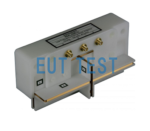
When testing for the ISO11452-8 standard, a standard low frequency magnetic field immunity test system is required as shown below (contact EUTTEST for more information on this system).

How to use ISO 11452-8
Current path analysis:
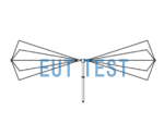
The low-frequency sine wave signal generated by the signal source is amplified by the amplifier, then enters the matching network for impedance matching and adjustment, and finally flows through the Helmholtz ring antenna HHS 5206-16 and generates a magnetic field in the middle of the ring, and the monitoring ring antenna receives the magnetic field generated by the Helmholtz coil ring and transforms it into a voltage value, which is required to be analyzed by the operator to analyze the specific value of the magnetic field in order to analyze whether or not it meets the standard requirements.
The above is the Helmholtz coil in ISO11452-8 current analysis, for other types of Helmholtz coils work in a similar way, but the process will involve a sequence of analysis and calculations, if the calculation is wrong or wiring errors, there may be high current damage to the equipment or the health of the people involved in the health risk, so build the system should be looking for a professional equipment like EUTTEST Therefore, the system should be built with the help of a professional equipment integrator like EUTTEST.
Magnetic field strength distribution

Magnetic field strength in the cross-section plane of a Helmholtz coil
The graph above depicts the magnetic field strength in the cross-sectional plane of HHS 5206-16. The coil current was set to 35 A. The results are shown in percentile of the maximum field strength generated in the inner region of the coil.The picture of HHS 5206-16 is overlaid and the two axes x and r are highlighted in green and red, respectively. The magnetic field flux was analyzed along these x and r axes.
From the analysis of the x and r axes below, it is known that the Helmholtz antenna should be used in such a way that the EUT is within the r axis of the ring in order to achieve a field strength similar to that of a linear one. If used only for HF the difference in effect between the two axes is not significant.
The above is an introduction to the selection and use of test equipment related to Helmholtz coils.