Introduction:
A100-1 set and A100-2 set are both produced by German langer company and authorized by Shenzhen EUTTEST agent sales products, bandwidth is DC-25 kHz, A100-1 set and A100-2 set are two different combinations of models, they contain the same type of accessories, but the number of different.
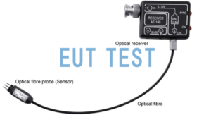
A100-1 set Combination set containing 1 x AE100 optical receiver and 1 x AS100 photoconverter;
A100-2 set Combination set containing 2 x AE100 optical receivers and 2 x AS100 photoconverters.
<<<<提醒:左右滑动表格>>>>| Model number | optical receiver | Optical converter | make a distinction |
| A100-1 set | 1 AE100 | 1 AS100 | Test 1 pin at a time |
| A100-2 set | 2 AE100 | 2 AS100 | Test 2 pins simultaneously |
Let's start with a detailed description of the accessories they all contain, AS100
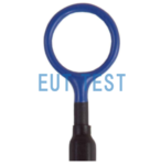
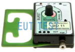
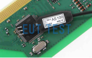
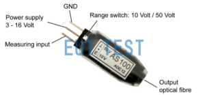
AS100 photoconverter:
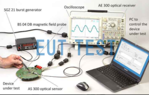
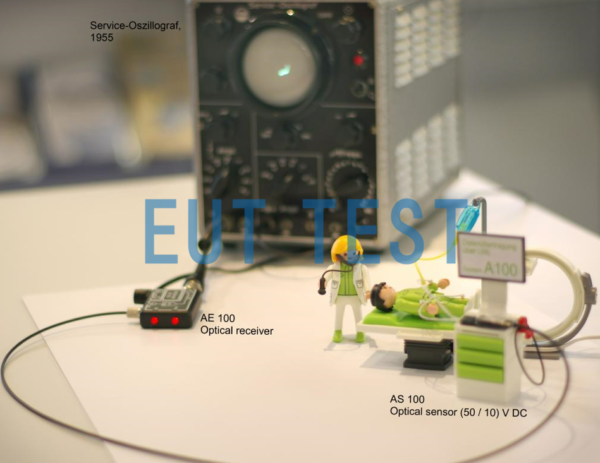
The sensor AS100 measures the analog signals in the EUT and converts the measured analog signals into optical signals. The optical signals are transmitted via fiber optics to the optical input of the oscilloscope, which in turn converts the optical signals into electronic analog signals for the optical receiver AE100.The oscilloscope can display these signals or use them to control other devices.
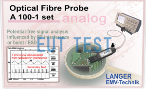
The AS100 can display analog signals under the influence of EFT/ESD/HF interference onto an oscilloscope. It is particularly suitable for testing analog signals when testing the immunity of electrical or electronic equipment to high frequency electromagnetic fields (IEC 61000-4-3 to IEC 61000 -4-6). A given modulation of an electromagnetic field will have an effect on the analog signal, and the A100, A200 and A300 series analog signal measurement systems are able to quickly identify these effects. The probe contains a sensor that measures the analog signal in the object under test and converts the measured analog signal into an optical signal. The optical signal is transmitted via fiber optics to the optical input of the oscilloscope; the optical input converts the optical signal into an electrical analog signal. The oscilloscope can display these signals or use them to control other devices.
How to use 🡪Langer-emv Analog to Fiber Optic Signal Sensor Usage
Technical parameters:
The following technical data sheets are common to Langer's A100-1 set and A100-2 set:
<<<<提醒:左右滑动表格>>>>| bandwidths | DC -25 kHz |
| sampling rate | 125 ksps |
| resolution (of a photo) | 12 Bit |
| AE 100 Optical Receiver | |
| bandwidths | DC -25 kHz |
| Optical input: fiber optic | Ø 2.2 mm |
| Output Voltage Range | 0 V - 10 V |
| Supply Voltage | 12 V -16 V |
| Current Input | ≈ 30 mA |
| output interface | BNC |
| AS 100 Optical Sensor | |
| bandwidths | DC -25 kHz |
| sampling rate | 125 ksps |
| Measurement range | 0 V . -50 V / 0 V - 10 V DC (switchable) |
| input resistance | 100 kΩ |
| radiation resistance | > 200 V/m |
| Supply Voltage | 3 V -16 V |
| Current Input | ≈ 3 mA |
| length of light | 1 m ... 20 m |