Digital Isolators - High Voltage Isolation: Safety Regulations, Standard Definitions and Test Methods
- Article Directory: Learn to Test Digital Isolators
Understanding the definition of high-voltage isolation parameters, their relevance to real-world applications, and the methods used to test them allows the system engineer to select the appropriate isolator for the design requirements.
Designs involving high voltage and high voltage isolation are very complex.
How much isolation does my system need?
What system-level isolation standards apply to my product or end device? Are there component-level standards to help me compare isolators and select the one that best fits my system-level needs? What parameters or metrics should I compare - there seem to be many? What test procedures does the isolation component go through to support the parameters in its data sheet? Most importantly, how do I ensure that I build a system that will operate reliably throughout the product's life cycle? These are questions faced by many system engineers dealing with high voltage and high voltage isolation.
- Maximum Transient Isolation Voltage (VIOTM) and Isolation Withstand Voltage (VISO)
- Maximum Repetitive Peak Voltage (VIORM) and Operating Voltage (VIOWM)
- Maximum Surge Isolation Voltage (VIOSM)
- Comparative Tracking Index ( CTI )
What are digital isolation chips & digital isolators?
In recent years, digital isolation chips are increasingly trusted by engineers in industrial, medical, automotive and other fields. Digital isolation chips are gradually replacing traditional optocoupler devices because of their remarkable features such as small size, high integration, low power consumption and high communication speed. Digital isolation chip is the core device in the system involving high-voltage safety, so it needs to be strictly screened when it leaves the factory.
Isolation is a means of preventing DC and unwanted AC currents from traveling between two parts of a system while allowing signals and power to be transmitted between those two parts. Electronic devices and semiconductor ICs used for isolation are called isolators. Modern electrical systems require isolation for a variety of reasons. Some examples are preventing electrical shock to a human operator preventing damage to expensive processors, ASICs, or FPGAs in high voltage systems, breaking ground loops in communication networks, and communicating with high end equipment in motor drive or power converter systems. Examples of applications requiring isolation include industrial automation systems, motor drives, medical devices, solar inverters, power supplies, and hybrid electric vehicles (HEVs).
Functional and Enhanced Isolation for Digital Isolators
When isolation is used to enable the system to function properly, but is not necessarily used as a vibration barrier, it is referred to as afunctional isolation. If isolation provides adequate protection against electric shock, as long as the insulating barrier is intact, it is called aprimary isolation. Safety regulations require that basic isolation be supplemented by secondary isolation barriers for redundancy so that the additional barriers provide protection against vibration even if the first barrier fails. This is called double isolation. For a compact and cost-effective system, it is preferable to have only one level of isolation with the required electrical strength, reliability, and vibration protection of two levels of basic isolation. This is calledEnhanced isolation.. The high voltage isolation performance of an isolator is quantified at the component level by parameters such as maximum repetitive peak voltage (VIORM), operating voltage (VIOWM), maximum transient isolation voltage (VIOTM), isolation withstand voltage (VISO), maximum inrush isolation voltage (VIOSM), and comparative tracking index (CTI). These parameters represent the isolator's ability to handle high voltage stresses of varying magnitude and transient profile and can be mapped directly to actual operating conditions. Definitions and test methods for these parameters are described in component-level standards such as IEC 60747-5-5, VDE 0884-10 and UL1577. The test methods are slightly different for basic and reinforced isolators, the latter being more stringent. vde 0884-10 is particularly applicable to magnetic and capacitive pairs or isolators. When isolators are used in practical applications, system and final equipment standards also require certain minimum values for these isolation parameters, depending on the system line voltage and whether basic or reinforced isolation is required.
- IEC 61800-5-1 (safety standard for adjustable speed electrical drives),
- IEC 60664-1 (Coordination of insulation of equipment in low voltage systems) and
- IEC 61010-1 (Safety standard for measuring, control and laboratory equipment)
are examples of system and final equipment standards. This document discusses in detail the definitions of the above high voltage isolation parameters and their relevance to real system scenarios, and describes how to test and certify these parameters. This understanding is critical for comparing the performance of competing isolation solutions, determining whether an isolator meets system-level isolation requirements, determining whether an isolator can be used for enhanced isolation, and judging the long-term reliability of an isolator.TI's ISO7842 is a robust electromagnetic compatibility (EMC), high-speed, high common-mode transient immunity (CMTI), four-channel enhanced digital isolator. It uses capacitor-based isolation with silicon dioxide (SiO2) as the dielectric.
The devices offer industry-leading high voltage and electrical performance, utilizing advanced processing techniques, precise packaging and innovative circuit design.
This document discusses the test procedures and results of the high voltage testing on the ISO7842. The test results demonstrate the excellent high voltage performance and reliability of the device, allowing system engineers to confidently solve even the toughest isolation problems.
Maximum Transient Isolation Voltage and Isolation Withstand Voltage
Both Voltage Isolated at Transient Maximum (VIOTM) and Voltage Isolated withstand (VISO) are designed to quantify the isolator's ability to handle high voltages through the isolation barrier for very short periods of time. During normal operation, the stress voltage across the isolation barrier is limited by the maximum system line voltage. However, unintentional disturbances in the system (e.g., arcing or noise on the power supply due to load variations) may briefly cause the voltage across the isolator to be several times the line voltage. The isolator should be able to handle these transient overvoltages without damage.
VIOTM is defined by IEC 60747-5-5 and VDE 0884-10 as the peak transient voltage that an isolator can handle without breaking down. During the certification process, the isolator is partially discharged by stressing the VIOTM for 60 seconds, followed by a 10-second partial discharge test at 1.6 times the VIORM (see the next section for the definition of VIORM). This is referred to as the Method A test.
VIOTM is tested for one second during manufacturing by stressing each VIOTM device for one second and then performing a partial discharge test at 1.875 times VIORM. This is called Method B1 testing. Partial discharges are localized discharges within an insulating material that indicate insulation integrity. ForFor more detailed information on the Method A and Method B1 test profiles, see the appendix at the end of this document.
The VIOTM value can also be used to determine compliance with system-level standards such as IEC 60664-1, which requires that the insulating barrier be able to tolerate a certain level of temporary overvoltage, depending on the system voltage, for up to 5 seconds. For example, VIOTM isolators greater than 6222 Vpk (4400 Vrms) meet the IEC 60664-1 standard for temporary Vpk overvoltages at line voltages up to 1000 Vrms. VISO is defined according to UL 1577 as the value of voltage rms that an isolator can handle for 60 seconds. During certification, tests are performed by applying VISO's sinusoidal stress for 60 seconds. In production, VISO is tested by stressing each device 1.2 times VISO for one second. For sinusoidal stress, VIOTM and VISO are equivalent.
Test Example:
TI tests its digital isolators for compliance with UL, IEC, and VDE requirements. To test for VIOTM or VISO, use the HT9464 High Voltage Isolation Test System or HT9464M Isolation Voltage and Partial Discharge Test SystemThe device is capable of applying the required transient overvoltage profiles according to Method A and Method B1 and measuring partial discharges. This test is performed by connecting all pins of the first side and side two and then applying voltage to the isolation barrier (Figure 1 )to executeThe
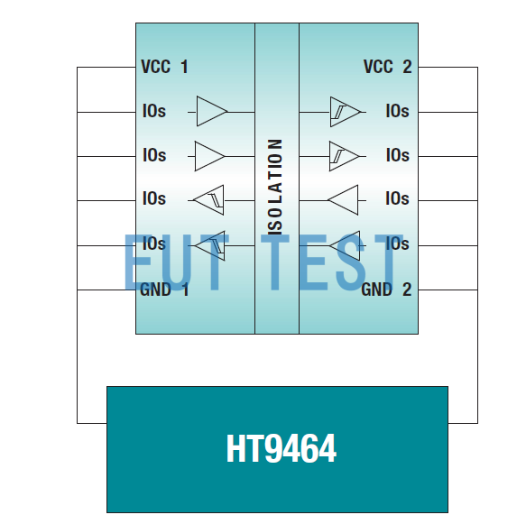
Figure 1: The HT9464 is used to test VIOTM and VISO: maximum transient isolation voltage (VIOTM) and isolation withstand voltage (VISO).
VIOTM defined by IEC 60747-5-5 and VDE 0884-10
VISO as defined by UL 1577
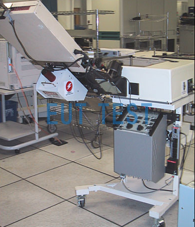
HT9464 Production Test with Autoprocessor Interface
TI's ISO7842 meets VISO of 5700 Vrms per UL and 8000 Vpk per VIOTM of VDE0884-10 and IEC 60747-5-5. Vpk This is based on Method A testing of more than five wafer farms and a total of more than 2000 devices. In addition, each ISO7842 device will be production tested according to Method B1 with stress voltages greater than 6840 Vrms to meet UL requirements. These levels of VISO and VIOTM are the highest available for any isolator in the industry in a standard 16-pin SOIC package.
It is important to note that ISO 7842 easily meets the 4400 Vrms requirement for the temporary overvoltage required for enhanced isolation for line voltages up to 1000 Vrms according to IEC 60664-1....
Maximum Repeat Peak Voltage and Operating Voltage
Both Voltage at Repetitive Peak Maximum (VIORM) and Operating Voltage (VIOWM) are designed to quantify the ability of an isolator to handle high voltages across its barriers continuously and routinely over its entire life cycle.
For example, an isolator used to provide gate control for a high-side IGBT in a motor drive system will see periodic trapezoidal potential differences across its isolation barrier as the auxiliary side of the isolator is referenced to move up and down between the high voltage DC rails. This trapezoidal stress is present whenever the motor is running.VIORM and VIOWM are defined in IEC 60747-5-5 and VDE 0884-10.VIORM is defined as the maximum repetitive peak voltage that the isolator can withstand, while VIOWM is defined as the maximum rms, or equivalent dc, voltage that the isolator can withstand over a specified long period of time. For sinusoidal stress voltages, VIORM and VIOWM are equivalent. These two values are specified by the isolator manufacturer based on manufacturer's testing.
VDE 0884-10 Ed 1.0 and IEC 60747-5 check VIOWM and VIORM by means of a partial discharge test, which examines partial discharges within the insulation, indicating degradation of the insulation. The partial discharge test is performed in conjunction with the VIOTM test, using Method A testing during certification and Method B1 during production testing.The upcoming VDE 0884-10 Ed 2.0 also includes additional requirements for VIORM and VIOWM. In order to comply with this new upcoming standard, manufacturers of enhanced isolators must provide the certification body with accelerated stress test data demonstrating that the isolator is capable of handling 1.2 times VIOWM/VIORM for more than 37.5 years During the accelerated stress test, the isolator is subjected to varying degrees of high voltages, well above its intended operating voltage, and the corresponding failure times are recorded. The voltage versus time curves were then extrapolated to make life predictions at the expected operating voltage. For isolators using silicon dioxide (SiO2) as an insulating material, the relationship between failure time and stress voltage is exponential. Therefore, the expected time-to-failure log decreases linearly when voltage stress is applied. Therefore, VDE 0884-10 Ed 2.0 requires that SiO2-based isolators use the same relationship as curve-fitting accelerated test data.
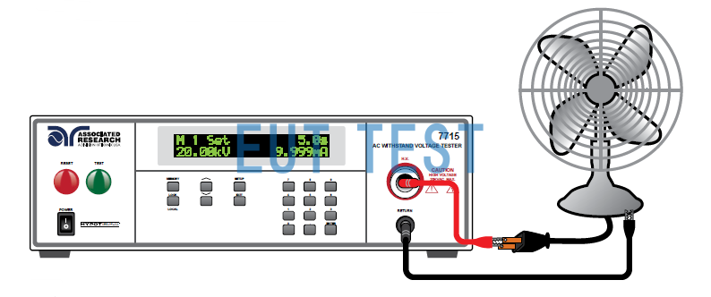
seek2 Shows the test setup used to perform the Accelerated Stress Survival test. All terminals on one side of the isolator are shorted together and all terminals on the second side of the isolator are shorted together. The desired high voltage, 60 Hz sine wave, is applied between one side and the second side using a high voltage source (such as a AR 7715 High Voltage Insulation Tester) Stress the isolation barrier. Apply stress voltages continuously until the impedance from one side to both sides drops below 4 MΩ. At each voltage point, batches of at least 32 devices were stressed. Device failure times fit well with the Weibull distribution, and statistical analysis was used to find the failure times corresponding to <1 ppm failure rates. This time is then plotted on a voltage versus failure time plot. This process is repeated at different voltage points to generate the entire voltage vs. time-to-failure curve. When this curve was extrapolated to be greater than 37.5 years and further de-estimated by a factor of 1.2, the value of VIOWM/VIORM was given. For a more complete understanding of accelerated stress testing and related extrapolations, refer to the VDE 0884-10 Ed 2.0 standard. Accelerated stress test at elevated temperature (150°C) and room temperature (25°C) VDE 0884-10 Ed 2.0 requires that the VIORM and VIOWM values from the accelerated stress test provide greater confidence in the long term reliability of isolators subjected to continuously applied high voltage. The same cannot be said for the partial discharge tests specified in IEC 60747-5-5 and VDE 0884-10 Ed 1.0, since there is no established relationship between long-term withstand capability and partial discharge.
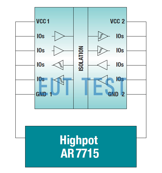
Figure 2: AR7715 Accelerated Stress Life Test setup.
AR 7715 Test Connection Diagram
Figure 3Shows ISO7842 life expectancy projections based on accelerated stress testing of isolation barriers used in five different wafer farms and a total of more than 2,000 devices. The shaded area indicates the safe operating area (SOA) for this device. Note that actual test data is intentionally not shown in the figure. the SOA includes the 1.2 de-rating factor required by the standard and is based on a more conservative statistical extrapolation than required by the standard. the SOA can be used to estimate life expectancy for any given operating voltage.
The <<1 ppm line indicates that less than one in a million devices is expected to be outside the SOA. The SOA curve in Figure 3as shownTi's ISO7842 can withstand 2121 Vpk of VIORM and 1500 Vrms of VIOWM for over 40 years. These levels of VIORM and VIOWM are the highest offered by any isolator in the industry in a standard 16-pin SOIC package.
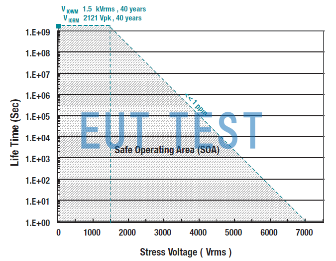
Figure 3: Maximum Repetitive Peak Voltage (VIORM) and Operating Voltage (VIOWM) for ISO7842.
Maximum surge isolation voltage
The Voltage Isolation Over Surge Maximum (VIOSM) quantifies the ability of an isolator to withstand very high voltage pulses of a specific transient profile. The surge test profile is shown in Figure 4 as shown. Surge voltages can result in installations due to direct or indirect lightning strikes, faults and short circuit events. Isolators claiming a specific VIOSM according to IEC 60747-5-5 and VDE 0884-10 must pass a surge test with a peak voltage of 1.3 times the VIOSM for basic isolation and 1.6 times the VIOSM for enhanced isolation. An isolator can only be called an isolator at the component level if it passes a surge test above 10 kV at the component level. The surge test pass level is also used to determine compliance with system level standards such as IEC 61800-5-1, which require a certain surge capability for a given system voltage.
For example, for equipment connected directly to the mains power supply (known as Class III) and operating at 600 Vrms line voltage, IEC 61800-5-1 requires a minimum surge capability of 8000 V for enhanced isolation.
Note that passing a surge test at levels greater than 10 kV has been widely used as the gold standard for enhanced isolation, although system level standards allow lower surge capability values for systems with lower line voltages.
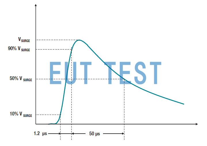
Figure 4: Surge pulse contours.
seek5 shows the setup used to test surge performance on the ISO7842. The isolator is configured as a double-ended device by shorting all left pins to one set and all right pins to the other. The isolator is configured as a double-ended device using the MIG1203 or MIG2403 (EMCPARTNER's MIG1203 and MIG2403 have been discontinued, replacement models)INS-1250 Serial Products(Contact EUTTEST for more information.) The surge generator applies a surge voltage across the isolation barrier, depending on the required test voltage.
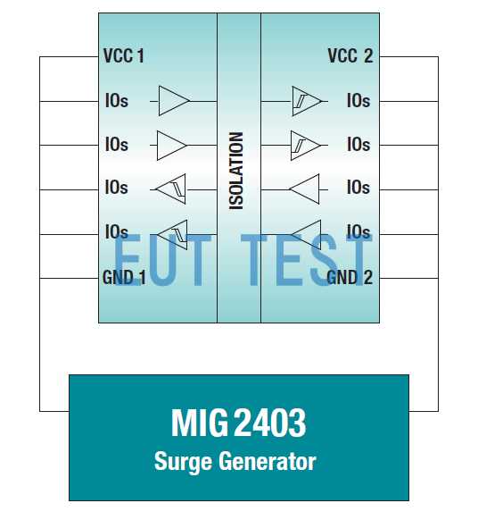
Figure 5: MIG2403 surge isolation voltage test setup.
Tests are performed by applying 50 pulses to each of the positive and negative polarities of the rated stress voltage. After the surge test, the device is subjected to a partial discharge test, insulation impedance test, and full-function production test for each method B1. A device is considered to have passed the surge test if it successfully passes all of these tests after the surge voltage is applied. To avoid arcing in air, this test is performed in dielectric oil. iso 7842 passes the surge voltage test with a voltage greater than 12800 V based on testing of more than 5 wafer locations and a total of more than 2000 devices. Since this exceeds 10 kV, it meets the limits for enhanced isolation. Based on the scaling factor of 1.6 required for enhanced isolation, the VIOSM is rated at 8000 V. Passing the 12800 V surge test also means that the device meets the surge criteria for enhanced isolation of equipment connected directly to the mains supply with line voltages of up to 1000 Vrms, according to IEC 61800-5-1.
Comparison of Leakage Trace Index
Comparative Tracking Index (CTI): The maximum voltage at which the surface of a material can withstand 50 drops of electrolyte (0.1% aqueous ammonium chloride solution) without forming a leakage trace, in V. The standard IEC 60112 specifies thatTest Methods. The test method is as follows:On a circuit board with a bare substrate, the panel is stabbed at two points 4mm apart again in a direction of 60° under a force of 100g. Two electrodes with their tips at an angle of 30 ° with the horizontal plane, the panel in the stabbing between the two points we have chosen to continuously drop 0.1% of sodium chloride solution, every 30s a drop, and pass 100V600V alternating voltage. You can first try 300V voltage and control the current for 1A, because at this time there is sodium chloride solution on the mixing surface, there is resistance, so it will be hot, the heat will make the solution evaporate, and then continue to drop sodium chloride solution until 50 drops of time, at this time to observe whether the plate itself leakage. Once the insulating plate appeared more than 0.1A leakage current and duration of more than 0.5s above, that is recorded as a fault, at this time the general buzzer will call, the test instrument will automatically record the number of drops of sodium chloride solution has been dropped at this time. If not, then continue to increase the voltage, until the failure, and record, and finally let the failure of the voltage for its CTI data.
When an isolator is placed on a motherboard as part of the final device, in addition to its internal isolation parameters, the mold compound used in its package is also important. This is because when high voltages are applied to the isolator, discharges at or near the package surface may cause localized deterioration of the die compound, resulting in a partial conduction path from one side of the isolator to the other. This phenomenon is called tracking. The ability of a material to withstand tracking is quantified by the Comparative Tracking Index (CTI).
IEC 60664-1 categorizes materials into four material groups based on their CTI values:
| Material Group I: | 600 V < CTI |
| Material Group II: | 400 V < CTI < 600 V |
| Material Group IIIA: | 175 V < CTI < 400 V |
| Material Group IIIb: | 100 V < CTI < 175 V |
CTI plays an important role in determining the minimum creep at the surface of the isolator or the shortest distance from a pin on one side of the isolator to a pin on the other side. Depending on the level of contamination present in the system environment, minimum creep is required for a given operating voltage. The use of mold compounds with a higher CTI allows the use of smaller packages and saves board space. For example, according to IEC 60664-1, a package with 8 mm creep using CTI-I mold compounds can withstand operating voltages up to 1600 Vrms of, whereas the same package using CTI-IIIa mold compounds can only withstand 800 Vrms.
The ISO7842 uses CTI-I mold compounds. This means that it can actually enable 1500 Vrms operating voltage at the system level in a standard 8 mm creeping SOIC-16 package. In contrast, competing isolators using CTI-IIIa mold compounds in the same package can only achieve 800 Vrms operating voltage at the system level, even though they may be able to claim higher values of VIORM/VIOWM at the component level.
Insulation penetration distance
Distance through insulation: the minimum straight-line distance between two metal parts in a tool with additional insulation or reinforced insulation.
The Distance Through Insulation (DTI) distance is the minimum distance between two voltage domains in an isolator inside an isolation package. Many end-equipment standards, such as IEC 60601-1 (Standard for Medical Electrical Equipment), specify the minimum required distance to be achieved by insulation.
However, these standards have provisions for allowing thinner insulation layers as long as they pass certain tests. These tests are a subset of the type tests required by VDE 0884-10. Historically, the higher DTIs were based on a direct indication of isolation performance based on the insulation used. However, since newer generations of magnetic and capacitive isolators use higher quality insulating materials, very high isolation performance can be achieved with much smaller DTIs.
The minimum internal DTI of the ISO7842 is 21 μm, with a typical DTI of 25 μm. However, the decomposition strength of the dielectric material used, SiO2, is very high at 800 V/μm. The dielectric quality used is the reason for the excellent high voltage performance of the device. The device complies with the enhanced isolation type test standard VDE 0DE 0884-10, proving that a DTI of 25 μm is not a problem with materials having a decomposition strength of 800 V/μm.
Table 1.ISO7842 Performance Summary
| serial number | causality | (an official) standard | (be) worth |
| 1 | Viso | UL1577 | 5700Vrms |
| 2 | Viotm | VDE 0884-10 Ed1.0=2.0 | 8000Vpk |
| 3 | Viorm | VDE 0884-10 Ed1.0=2.0 | 2121 Vpk (>40 years) |
| 4 | Viowm | VDE 0884-10 Ed1.0=2.0 | 1500 Vrms (>40 years) |
| 5 | Viosm | VDE 0884-10 Ed1.0=2.0 | 8000 V (Surge Test Pass Level) (>12.8 kV) |
| 6 | CTI | IEC 60664-1 | CTI >600 Material Group: I |
| 7 | Dti | NA | 21 µm (min) / 25 µm (type) Note: The subdivision field for SiO2 is 800 V/µmµm |
Maximum Transient Isolation Voltage (VIOTM) and Isolation Withstand Voltage (VISO)
Maximum Repetitive Peak Voltage (VIORM) and Operating Voltage (VIOWM)
Maximum Surge Isolation Voltage (VIOSM)
Comparative Tracking Index ( CTI )
Notes:
1. The ISO7842 also complies with the VISO, VIOTM, VIORM and VIOWM values mentioned in Table 1 (IEC 60747-5-5). However, the ISO7842 will not be certified to IEC 60747-5-5 because the standard is specific to optocouplers, not capacitive couplers.
2. VDE 0884 Ed 2.0 (forthcoming) is a revision of VDE 0884 Ed 1.0. Compared to IEC 60747-5-5 and VDE 0884 Ed 1.0 indicating VIOWM and VIORM, it has stricter constraints and additional requirements.
reach a verdict
The high-voltage isolation performance of an isolator is quantified by different parameters that indicate the isolator's ability to handle high-voltage stresses of varying amplitude and transient profile. Various component-level standards define these parameters and methods for testing them. This white paper discusses in detail the definition of these parameters, their relevance to real system scenarios, and describes how to test and certify them.
Presents test results for the TI ISO7842 Enhanced Digital Isolator that were performed according to standard procedures. The device meets the transient overvoltage and surge requirements for enhanced isolation at the component and system levels and provides years of reliable operation at continuous high operating voltages. Test results show that the device represents a significant leap forward in TI's capacitive high-voltage isolation capabilities, while providing industry-leading high-voltage performance.
references
1. IEC 60747-5-5 Ed 1.1, Semiconductor devices - Discrete devices - Part 5-5: Optoelectronic devices - Optocouplers, May 2013
2. DIN V VDE V 0884-10 Ed 1.0, Semiconductor Devices - Magnetic and Capacitive Connectors for Safety Isolation, December 2006
3. UL 1577 Ed 4.0, Safety Standard for Optical Isolators, May 2000
4. IEC 61800-5-1 Ed 2.0, Adjustable Speed Electric Drive Systems, Safety Requirements, Electrical, Thermal and Energy, July 2007
5. IEC 60644-1 Ed 2.0, Insulation harmonization of equipment within low-voltage systems, principles, requirements and tests, April 2007
6. IEC 61010-1 Ed 3.0, Safety requirements for electrical equipment for measurement, control and laboratory use, general requirements, June 2010
7. ISO7842 product folder
8. ISO7841 product folder
9. ISO7821 product folder
10. Enhanced isolation for unparalleled performance
11. Sarangan Varavan, Understanding Electromagnetic Compliance Testing in Digital Isolators.
Texas Instruments White Paper, November 2014
appendice
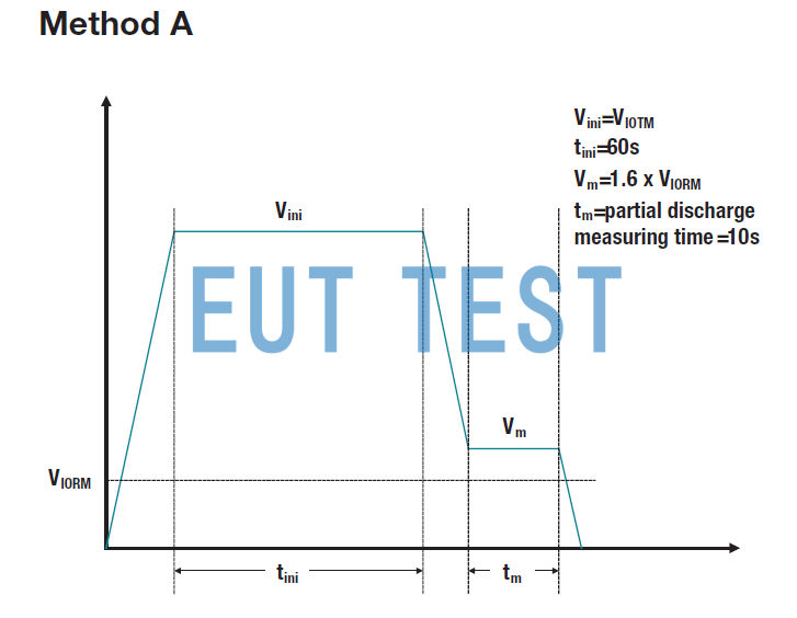
Figure 6: Simplified Method A test profile.
Maximum Transient Isolation Voltage (VIOTM)
Maximum Repetitive Peak Voltage (VIORM)
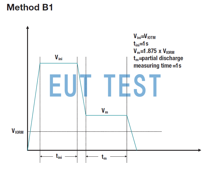
Figure 7: Simplified Method B1 test profile.
Maximum Transient Isolation Voltage (VIOTM)
Maximum Repetitive Peak Voltage (VIORM)
IMPORTANT NOTE: The products and services of Texas Instruments (TI) and its subsidiaries described herein are subject to TI's standard terms and conditions of sale, and customers are advised to obtain the most current and complete information about TI products and services before placing an order. Customers are advised to obtain the most current and complete information about TI's products and services before placing an order TI assumes no responsibility for application assistance, customer application or product design, software performance, or patent infringement. The posting of information about any other company's products or services does not constitute an approval, warranty or endorsement by TI. SLY063A
Author:
Anant S Kamath ,Systems Engineer, Isolation, Interface Group Texas Instruments.
Kannan Soundarapandian, General Manager, Motor Drivers Texas Instruments.
- Created Date: 2024-08-16 10:10:44 ;
- Last modified on 2024-08-16 18:10:44 ;