Langer AS100 AS200 AS300 Analog to Fiber Optic Sensor Usage
- Article Directory: Guidelines for the use of test instruments
The following is the complete use of Germany langer-emv analog to fiber optic signal sensor to oscilloscope show up written by EUTTEST for you, if you have any questions after you buy this product from our company you can contact the sales staff for advice.
This instruction for use relates to langer-emv products:
A100-1 set and A100-2 set; both contain the AS100
A200-1 set and A200-2 set; both contain the AS200
A300-1 set and A300-2 set; both contain the AS300
How to use the analog to fiber optic combo kit:
Recognizing Sensor Connection Diagrams Connection Diagrams
The AS100, AS200, and AS300 all three AS serial sensors are wired and powered using the diagram below.
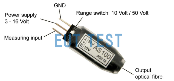
Connection diagram for AS100, AS200, AS300
2、Connect the real analog signal
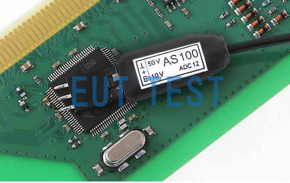
By connecting an AS serial sensor to the pins of the IC or component under test, the analog signal will be converted to an optical signal.
Connect the A200-1 to the pins of the IC or component under test and the analog signal will be converted to an optical signal
3、Connect the tail fiber to the fiber optic receiver
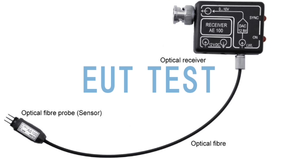
Connect the tail signal of the AS sequence sensor to the fiber optic receiver AE sequence
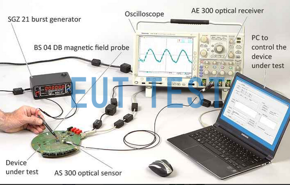
4. Connect the fiber optic receiver AE sequence to the oscilloscope
AE sequences include AE100, AE200, AE300.
Connecting the Fiber Optic Receiver AE Sequence to an Oscilloscope
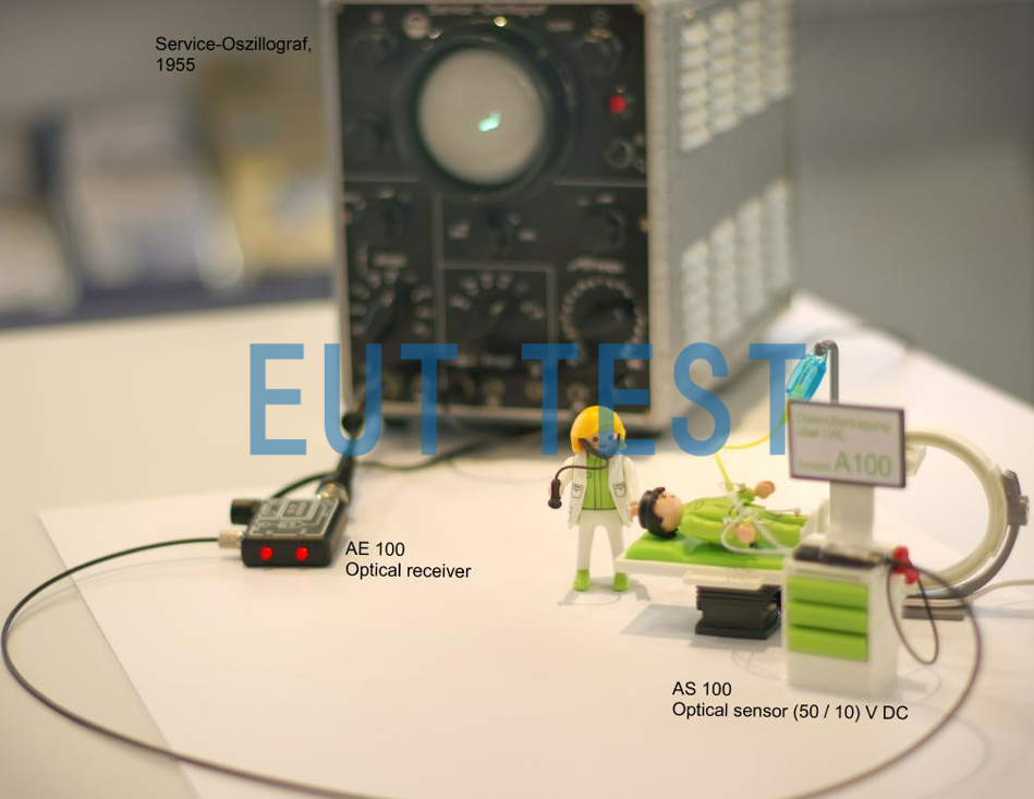
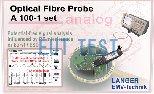
AE Sequence and AS Sequence practical use of the effect picture
Other uses:
EMC engineers can also use E1 anti-interference development system when using analog to fiber optic signal sensor to monitor the EUT on a pin are affected by the E1 pulse interference detection. According to the above process to connect the EUT pins and oscilloscopes, the use of E1 in the PCB location of interest to inject interference signals.
For more product information, please click -> E1 Anti-jamming Development System.
AS100 and E1 are used together to detect the pulse interference waveform from E1.
- Created Date: 2024-08-26 06:39:36 ;
- Last modified on 2024-08-26 14:39:36 ;