IC EMC Integrated Circuit Electromagnetic Compatibility Test System
- Article Directory: How to test integrated circuits for electromagnetic compatibility
I. Introduction:
In the past, EMC compatibility has been a module-level or system-level issue for electronics.
Electronic equipment manufacturers are now beginning to require semiconductor manufacturers to specify emission and immunity levels for integrated circuits (ICs). Some semiconductor companies have responded by developing proprietary test methods, while others have worked with equipment manufacturers and the International Electrotechnical Commission (IEC) to develop some general-purpose standardized methods for IC EMC testing and measurement.
II.IC EMC problem sources:
In addition to wiring and structural design, the characteristics of the IC used in the device also determine its EMC characteristics. the sensitivity of the IC to fast pulses increases significantly with its structure size, operating voltage, and fewer operating points. The current field of IC and microcontroller development is converging towards structures smaller than 100nm, and even computer chipsets have reached 7nm, and the accompanying higher switching rates have resulted in a decrease in the EMC-EMS immunity of ICs compared to earlier products by nearly 90%. This trend will ultimately be reflected in the EMC characteristics of the device level. Therefore, for ICs with the same functionality, good EMC characteristics can increase the competitive advantage of IC manufacturers.
More on IC EMC Problem Sources
C. How to improve the competitiveness of IC's EMC compatibility?
3.1. Improving the EMC performance of IC integrated circuits should start with compliance with IEC standards:
In the absence of the appropriate capabilities and qualifications to plan EMC standards for their own products, IC manufacturers should first follow the International Electrotechnical Commission's IEC test standards. Then they should utilize the IEC standards to develop their own corporate standards for their products.
Now, IEC Technical Committee TC 47 (Semiconductor Devices) is leading the IEC's work. The committee assigned work on the EMC measurement standard to its subcommittee (SC) 47A+ Integrated Circuits.TC 47/SC 47A created Working Group (WG) 9 to prepare test and measurement methods.The WG9 work program cooperates with other industry and national standards bodies such as the Society of Automotive Engineers (SAE) and VDE (VDE) of Germany. (VDE) in Germany. Like the EMC standards at the product and equipment level, IC-EMC includes a family of standards for two tests, RF EMI and RF Immunity EMS.
3.1.1, IEC 61967-EMI Electromagnetic Emission Sequence Standard: (updated at 20200328)
IEC 61967-1:2018 RLV Integrated circuits - Measurement of electromagnetic emissions - Part 1: General conditions and definitions
IEC 61967-2:2005 Integrated circuits - Measurement of electromagnetic emissions, 150 kHz to 1 GHz - Part 2: Measurement of radiated emissions - TEM cell and wideband TEM cell method
Show all publications for "IEC 61967-4:2002+AMD1:2006 CSV Integrated circuits - Measurement of electromagnetic emissions, 150 kHz to 1 GHz - Part 4: Measurement of conducted emissions - 1 Ω/150 Ω direct coupling method". 150 kHz to 1 GHz - Part 4: Measurement of conducted emissions - 1 Ω/150 Ω direct coupling method
IEC 61967-5:2003 Integrated circuits - Measurement of electromagnetic emissions, 150 kHz to 1 GHz - Part 5: Measurement of conducted emissions - Workbench Faraday Cage method conducted emissions - Workbench Faraday Cage method
Show all publications for "IEC 61967-6:2002+AMD1:2008 CSV Integrated circuits - Measurement of electromagnetic emissions, 150 kHz to 1 GHz - Part 6: Measurement of conducted emissions - Magnetic probe method 150 kHz to 1 GHz - Part 6: Measurement of conducted emissions - Magnetic probe method
IEC 61967-8:2011 Integrated circuits - Measurement of electromagnetic emissions - Part 8: Measurement of radiated emissions - IC stripline method
IEC TR 61967-1-1:2015 Integrated circuits - Measurement of electromagnetic emissions - Part 1-1: General conditions and definitions - Near-field scan data exchange format definitions - Near-field scan data exchange format
IEC TS 61967-3:2014 Integrated circuits - Measurement of electromagnetic emissions - Part 3: Measurement of radiated emissions - Surface scan method
IEC TR 61967-4-1:2005 Integrated circuits - Measurement of electromagnetic emissions, 150 kHz to 1 GHz - Part 4-1. Measurement of conducted emissions - 1 Ω/150 Ω direct coupling method -Application guidance to IEC 61967-4
3.1.2, IEC 62132-EMS electromagnetic immunity sequence standard:
IEC 62132-1:2015 Integrated circuits - Measurement of electromagnetic immunity - Part 1: General conditions and definitions definitions
IEC 62132-2:2010 Integrated circuits - Measurement of electromagnetic immunity - Part 2: Measurement of radiated immunity - TEM cell and wideband TEM cell method
IEC 62132-3:2007 Integrated circuits - Measurement of electromagnetic immunity, 150 kHz to 1 GHz - Part 3: Bulk current injection (BCI) method injection (BCI) method
IEC 62132-4:2006 Integrated circuits - Measurement of electromagnetic immunity 150 kHz to 1 GHz - Part 4: Direct RF power injection method injection method
IEC 62132-5:2005 Integrated circuits - Measurement of electromagnetic immunity, 150 kHz to 1 GHz - Part 5: Workbench faraday method cage method
IEC 62132-8:2012 Integrated circuits - Measurement of electromagnetic immunity - Part 8: Measurement of radiated immunity - IC stripline method
IEC TS 62132-9:2014 Integrated circuits - Measurement of electromagnetic immunity - Part 9: Measurement of radiated immunity - Surface scan method
3.1.3, IEC 62215 EMS impulse immunity sequence standard:
IEC 62215-3:2013 Integrated circuits - Measurement of impulse immunity - Part 3: Non-synchronous transient injection method
IEC TS 62215-2:2007 Integrated circuits - Measurement of impulse immunity - Part 2: Synchronous transient injection method
3.1.4, IEC 62228 IC-EMC assessment methodology standard
IEC 62228 provides guidance on EMC evaluation methods and procedures for a number of products and references the test methods in sections 3.1.1 to 3.1.3 for testing.
IEC 62228-1:2018 Integrated circuits - EMC evaluation of transceivers - Part 1: General conditions and definitions
IEC 62228-2:2016 Integrated circuits - EMC evaluation of transceivers - Part 2: LIN transceivers
IEC 62228-3:2019 Integrated circuits - EMC evaluation of transceivers - Part 3: CAN transceivers
IEC 62228-5 ED1 Integrated circuits - EMC evaluation of transceivers - Part 5: Ethernet transceivers
PNW 47A-1092 Future IEC 62228-6: Integrated circuit - EMC Evaluation of transceivers - Part 6: PSI5 transceivers
IEC 62228-7 ED1 Integrated circuits - EMC evaluation of transceivers - Part 7: CXPI transceivers
3.1.5. other criteria:
IEC 62433-1:2019 EMC IC modelling - Part 1: General modelling framework
IEC 62433-2:2017 EMC IC modelling - Part 2: Models of integrated circuits for EMI behavioral simulation - Conducted emissions modelling (ICEM-CE)
IEC 62433-3:2017 EMC IC modelling - Part 3: Models of integrated circuits for EMI behavioral simulation - Radiated emissions modelling (ICEM-RE)
IEC 62433-4:2016 EMC IC modelling - Part 4: Models of integrated circuits for RF immunity behavioral simulation - Conducted immunity modelling (ICIM-CI)
IEC TR 62433-2-1:2010 EMC IC modelling - Part 2-1: Theory of black box modelling for conducted emission
IEC 63011-1:2018 Integrated circuits - Three dimensional integrated circuits - Part 1: Terminology
IEC 63011-2:2018 Integrated circuits - Three dimensional integrated circuits - Part 2: Alignment of stacked dies having fine pitch interconnect
IEC 63011-3:2018 Integrated circuits - Three dimensional integrated circuits - Part 3: Model and measurement conditions of through-silicon via
3.2. Test the EMC performance of ICs using test equipment and test methods that comply with IEC test standards.
With 深圳市易优特测试技术有限公司's German langer-emv IC test system, users can create a realistic EMC environment during the development process by injecting pulses of various parameters, so that IC circuit designers can easily see the effects of IC on various types of interference and improve the chip design. This allows IC circuit designers to easily see the impact of ICs on various types of interference and improve the design of the chip.The IC test system can adequately protect the sensitive and fragile pins on the IC during testing.
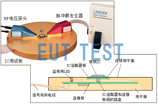
Injection of pulse interference into IC test systems using langer-emv for ICs
IC-EMC test equipment product line:

List of IC-EMC test categories and test instruments

Types of Impulse Interference for IC-EMC
This article does not describe all the equipment in the above table in detail, you can directly in the EUTTEST website search for products in the above model (such as P600) to find specific product technical parameters and test methods.
The following is also a continually updated list of available product descriptions:
P603 Integrated Circuit Test System High Frequency IC Pin Current Conforms to IEC 61947-4
P603-1 Integrated Circuit Test System High Frequency IC Pin Current Conforms to IEC 61947-4
P750 Integrated Circuit Test System High Frequency IC Pin Voltage Conforms to IEC 61947-4
S603 Integrated Circuit Test System High Frequency IC Pin Current Conforms to IEC 61947-4
S750 Integrated Circuit Test System High Frequency IC Pin Current Conforms to IEC 61947-4
- Created Date: 2024-08-26 10:31:32 ;
- Last modified on 2024-08-26 18:31:32 ;