IC Integrated Circuit EMC DPI Test Methods
- Article Directory: How to test integrated circuits for electromagnetic compatibility
Preface:
The EMC standard for ICs (IEC 62132) provides three typical measurement methods for this type of characterization: the DPI (Direct Power Injection) method, the TEM cell (Transverse Electromagnetic Cell) method, and the use of IC strip lines.
This paper examines the DPI test method in more detail. In addition, it explains the limitations that are used as a starting point for extending the method.
The parameters obtained using the extended method describe the immunity of the IC to its actual future use.IC users can use these immunity parameters as a basis for selecting the appropriate IC for a particular electronic system and as a basis for EMC design in printed circuit board development. In addition, IC manufacturers can use this information to narrow down and eliminate weaknesses in their chips. This paper also provides a practical example of a LIN transceiver being checked using the extended DPI test method.
Further Developments in DPI Test Methods
According to IEC 62132-4 (Figure 1The DPI methodology has proven successful in practice in evaluating the EMC immunity of ICs.
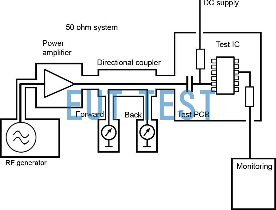
Figure 1 DPI-Methode nach der IEC 62132-4
RF is injected into individual IC pins via conduction coupling. the RF current flows from the power amplifier to the corresponding pin via a 50-ohm line and coupling capacitor. the strength of the RF interference is determined by the forward power measured using a directional coupler. Power is the correct parameter to physically evaluate if the RF-induced temperature rise in the IC causes it to fail.
However, other RF interference events may be unrelated to the power fed. For example, an oscillator may stop or demodulation may occur in an operational amplifier, transistor, or diode. These interference mechanisms depend only to a small extent on the power converted in the IC, but they are directly triggered by fundamental physical parameters such as RF currents and voltages (e.g., demodulation of RF currents). Interference voltages or currents are also the parameters responsible for driving the corresponding interference events in the device under test in other areas of EMC testing, such as burst or ESD testing. High currents or high voltages are not necessarily accompanied by high power.
When testing semiconductors, matching depends on the switching state. In addition, the switching edges and their own mismatch characteristics must be considered. The average PforwardPbackwardPower measurements do not provide any system information related to the u(t) and i(t) parameters. However, RF current and voltage variations over time are critical for gaining new insights such as identifying weaknesses in ICs and organizing countermeasures in IC design and printed circuit board development.
Measurement of interference with an ammeter and voltmeter
The ohmic resistance of a microcontroller power supply pin is usually very small. It can be in the range between milliohms and ohms. A capacitor of a few nF can be integrated into an IC that also provides impedance in the ohmic range at 100 MHz or higher. the line inductance of the IC produces similar values. As a result, the internal resistance of the IC is very low, so it may be much smaller than the 50-ohm source of a power amplifier. This means that the power amplifier operates under short-circuit conditions and then delivers maximum current. The feed current interferes with the IC function, but the wattmeter shows only a few milliwatts. As a result, the IC is evaluated as too weak and misclassified based on the power evaluation.
Other IC pins may also have impedances between milliohms and kilohms. The system is close to short-circuit conditions with IC impedance 50 ω. As is common practice in high voltage technology, immunity testing at quasi-open circuit voltages is not possible by injecting RF into the IC. Current and voltage conditions on the pins are based on the entire system and must be measured directly on the pins (Figure 2).
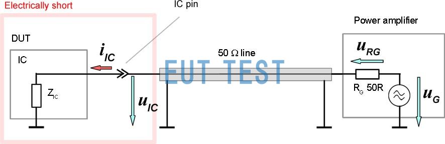
Fig. 2 Measurement setup for measuring current and voltage conditions on pins
This electrical short-circuit measurement setup avoids metrological difficulties with standing waves that may be generated on the line to the power amplifier.
This example clearly shows that RF current and RF voltage are decisive parameters for IC evaluation.
Figure 3respond in singingFigure 4The measurement settings are displayed (hereinafter referred to as " P500Probe Measurement System").
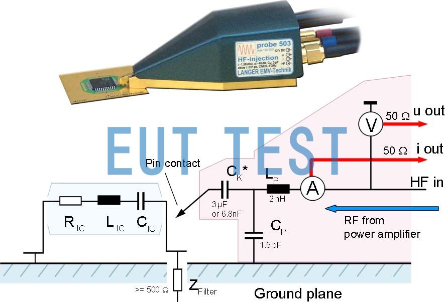
Figure 3 and Figure 4 Measurement setup with P500 probe
RF interference flows from the power amplifier into the IC pins through the connectedP500The probe is evaluated. The probe also incorporates an ammeter and voltmeter so that current, voltage and phase angle can be measured with an oscilloscope. The power, impedance and other parameters of the device under test can be calculated from the measured values.
The parameters obtained allow engineers to draw more detailed conclusions based on the EMC of the ICs in the respective electronic system. For example, failures that occur at high current strengths are usually due to magnetic coupling, while failures that occur at high voltages will be due to capacitive coupling. The new measurement methodology allows for the measurement of reactive currents that are normally undetectable by power measurements and provides detailed physical insights that would otherwise not be possible. This new RF injection method with integrated current and voltage measurements is highly beneficial for IC development.
LIN Transceiver Research
It can be done from theP500The results obtained from the probe measurement system derive an RF equivalent circuit for each individual IC pin. However, the impedance of the pin depends not only on the switching state of the signal, but also on the RF generator voltage. In theP500The probe is used to inject small amounts of RF levels into the pin. These disturbances must, for example, be low enough to prevent the protection diode from opening and additional current paths and components from becoming active. The resistance and reactance of the IC can be determined as a function of frequency based on U, I and φ values measured with an oscilloscope. If there is no dominant capacitive or inductive share, the reactance can be categorized as X Cand X LBy calculation. This requires measurements at different frequencies.
By analyzing the high frequency/low frequency current voltages on the pins of the IC, weak points of the IC can be identified. For example, high-frequency voltages may cause diode paths to open, resulting in impedance changes.
The measurement system can be used for a variety of practical analyses. For example, it allows the visualization of time-varying non-sinusoidal high-frequency current and voltage waveforms (Figure 5).
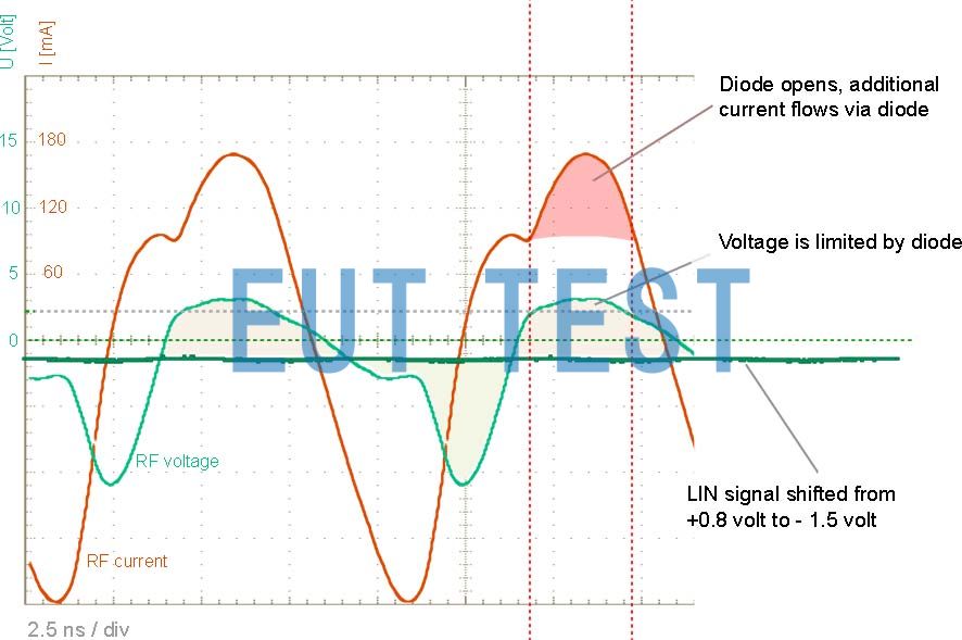
Figure 5 Time-varying non-sinusoidal high-frequency current and voltage waveforms measured with the P500 probe.
Once the forward voltage of the internal diode is reached, an additional current path opens. the impedance of the IC drops, the current increases, and the voltage can be limited (fed back to the supply network). When the diode opens, the new coupling path becomes active. The current flowing through the diode enters other parts of the network and acts there as rectifier current. These currents or voltages superimpose useful signals, such as trigger or control signals from the LIN driver, and cause the FET to enter a blocked, open or undefined state. By analyzing the currents and voltages as a function of time, the internal mechanisms of the IC can be further elucidated. Manufacturers can introduce targeted IC improvements, and users can derive EMC countermeasures for real-world IC use.
Conclusion of module development
For example, if RF current is coupled to sensitive pins through internal coupling paths in the layout, the sensitive IC may become a victim of interference.RF current can flow from the on-board network plug to the LIN transceiver via the appropriate line connection to the V batRF currents may also pass through the GND system to the GND pin, especially in the segmented GND of a two-layer printed circuit board. This coupling path can be blocked by making full contact with the GND system. Additionally, the isolation capacitor must be connected to the GND pin at V batThere are sufficient dimensions on the filter. A filter structure with one inductor and two filter capacitors (PI filters) is recommended. The filters prevent RF current from reaching sensitive pins. If the V batpins are very sensitive, then appropriate measures can be taken at the beginning of development.
Interference suppression on modules containing LIN transceivers is actually difficult because the individual pins that ultimately cause interference in the IC must be identified. The situation becomes unclear if the IC has several sensitive pins that are causing it to fail. The effectiveness of individual measures is hidden due to coupling to other pins. If the sensitive pins of the IC are known, reliable countermeasures can be taken in the right place even before the actual EMC work is started. As a result, EMC problems with ICs can be controlled more quickly and easily.
- Created Date: 2024-08-26 10:28:35 ;
- Last modified on 2024-08-26 18:28:35 ;