Radiant Antenna Usage
- Article Directory: Guidelines for the use of test instruments
Introduction:
Radiating antenna is a kind of test antenna used in the radio wave darkroom for receiving RF interference signals, according to the demand of EMC testing will use a variety of antenna types, such asmast antenna,Biconical antenna,Logarithmic periodic antenna,Horn Antennaand other antenna types. This article will describe how to correctly select and use the right antenna for EMC EMC radiated emission test methods, which are applicable to all test standard requirements.
How to choose an antenna type:
For the use of RF interference signal reception, we only need to select the antenna type according to the test frequency required by the test standard, please select the antenna type directly according to the following table:
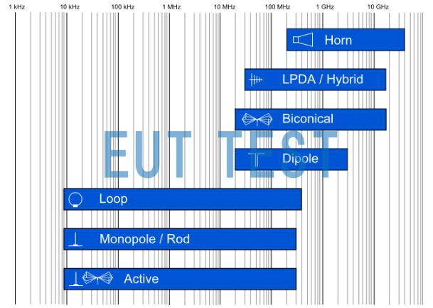
Selection of different types of radiating antennas for the reception of RF interfering signals
The chart above from 10kHz-40GHz identifies in blue the test frequencies corresponding to the different antenna types.
Radiating Antenna Usage - Minimum test distance between the radiating antenna and the DUT:
After selecting the antenna type, we then need to place the antenna in a dark room or shielded room with RF cable to connect to an external EMI receiver to start testing.
In order to facilitate understanding, we choose our company agent sales of BBHA 9120D The BBHA 9120D is a German antenna that has been used for many years in the field of antennas and antennas. Schwarzbeck A linearly polarized, high gain horn antenna with a typical test frequency range of 1 GHz to 18 GHz will be supplied with a factory specification document containing a picture of the minimum test distance between the radiated transmitter-receiver antenna and the object under test:
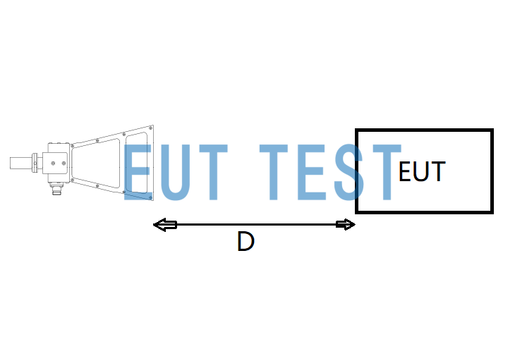
Definition of the minimum test distance between the radiated transmitter-receiver antenna and the DUT Picture
As you can see from the figure above, the test distance D for this antenna is defined as a consistent extension from the vertical cut of the top of the antenna to the surface of the EUT (object under test), so if you want to test a 1-meter test distance, just let D = 1 meter. Note that this test distance is variable.
Does a radiating antenna require moving the antenna to test the entire surface of the EUT?
It is certain that the radiating antenna must irradiate the entire EUT surface under test and keep the EMI receiver set to Max Hold MAX HOLD mode to get the maximum RFI level value. We need to calculate the angle of radiation antenna each time according to the factory data, and then according to the EUT test area to get how many times the antenna needs to be moved to complete the radiation interference measurement of the whole EUT surface.
Read the calibration calibration report data for the antenna:
We need to perform a calculation of the minimum opening angle of the radiated field (the worst case scenario in the antenna's operating frequency range should be considered).
Continuing with the BBHA 9120D example, the factory data for the 9120D, provided by EUTTEST, contains a minimum turn-on angle of about 7° at 18 GHz for both the electric and magnetic fields (see figure below).
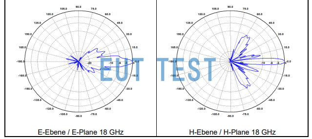
BBHA 9120 D Minimum opening angle of horn antenna for E and H fields at 18 GHz
Start calculating the angle of the radiating antenna for each shot
In order to cover the full width (x) of the EUT of the sample under test, the radiating antenna must be placed at a distance (d) measured from the horn antenna and the front plane of the EUT (see Figure 2). The distance "d" is given by the following equation:
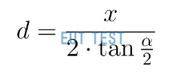
Test distance of radiating antenna - D Calculation formula
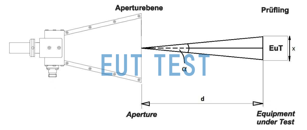
Radiant Antenna Test RE Test Distance Definition Chart for Radiant Emission
X = the size of the surface to be tested by the EUT;
α = opening angle of the antenna.
So based on the distance graph above, the antenna distance D formula, and the 3dB flap width table, you can calculate the minimum test distance of the antenna.
Example calculations:
For example, the surface width of the EUT is X=0.2m; the opening angle of the BBHA 9120D at 18GHz is 7°, and the minimum test distance d=1.635 meters can be calculated according to the formula in the previous section.
If this distance is compared to the military standard GJB151B-2013 or automotive electronics CISPR25 The RE test method of the test method, it can be learned that the width of the sample under test at the 1m test position can only be 0.122m at the maximum.
If the width of the product under test exceeds the minimum test distance of the radiating antenna:
The width of the product under test is not known, when the width exceeds the minimum test distance calculated above, such as 1 meter width, EMC testers need to be at least according to the following chart to the product surface is divided into five parts, each part of 0.2m were tested five times.

Radiant Antenna BBHA 9120D Requires five moves to test a 1-meter width DUT
Summary:
Above is the use of radiation antenna, including antenna selection and the definition of the test distance method, our company will provide all products for the purchase of customers door-to-door installation and training services, click on the instrumentation equipment above or search to get more available product models.
- Created Date: 2024-10-08 07:58:26 ;
- Last modified on 2024-10-08 15:58:26 ;